
System for decomposing events from managed infrastructures with semantic clustering

Active Publication Date: 2019-01-31
MOOGSOFT
View PDF4 Cites 2 Cited by
  • Summary
  • Abstract
  • Description
  • Claims
  • Application Information

AI Technical Summary

Benefits of technology

The present invention provides methods and systems for decomposing events from managed infrastructures with data-driven fault localization. This involves using semantic clustering to identify common factors and patterns in events that indicate failures or problems in the infrastructure. The system can create situations based on these events and identify common steps to help troubleshoot and fix issues in the infrastructure. Overall, the invention helps to quickly detect and address issues in managed infrastructures to improve operational efficiency and reliability.

Problems solved by technology

Because of the vast amount of information that is available on the web, it can be difficult for a person to locate information that may be of interest.
For example, a person who receives hundreds of electronic mail messages / events from infrastructure a day may find it impractical to take the time to store the messages / events from infrastructure in folders of the appropriate topic.
As a result, it may be difficult for the person to later find and retrieve all messages / events from infrastructure related to the same topic.
Because there may be no effective indexing of these groups, it can be difficult for the person to find groups related to the topic of interest.
Without an automated approach it is impractical to handle the massive amounts of web-based information that are being generated on a daily basis.
Moreover, because a person may not be fully aware of the entire web directory hierarchy or may not fully understand the semantics of information, the person may place the information in a directory that is not the most appropriate, making later retrieval difficult.
The large volume can more than difficult to manage and / or organize for most users.
However, this as well as other existing approaches present several problems.
For example, tasks are not visible to the user, or rather are “out of sight, out of mind”, and thus can be easily, if not frequently, neglected, overlooked, or forgotten.
Hence, the message cannot serve multiple activities at once.
Other current systems have attempted to ease these problems; however, they fall short as well for similar reasons.
This largely unnecessarily high volume of network traffic decreases worker productivity and slows down important network applications.
One of the most serious problems in today's digital economy has to do with the increasing volume of spam.
For example, one prior art methodology provides a centralized database for maintaining signatures of documents having identified attributes against which emails are compared, however, spammers now modify the content of their email either slightly or randomly such that the message itself may be intelligible, but it evades detection under various anti-spam filtering techniques currently employed.
Decomposing a traffic matrix has proven to be challenging.
Because such data centers typically host many multi-tier applications, the applications requests are overlapped, both in the spatial and temporal domains, making it very difficult for conventional pair wise statistical correlation techniques to correctly extract these interleaved but independent applications.
The number of applications is usually unknown a priori due to interleaving and overlapping application requests, which further imposes a challenge to discovery of the individual application sub-graphs.
Traffic tapping from switches is limited by the capability of switches as well as the monitoring hosts.
In addition, monitoring data collected over multiple switches, each with multiple ports may result in high-volume aggregate network traffic and potentially packet loss.
Both cases lead to significant loss in the monitoring data.

Method used


Image

  • System for decomposing events from managed infrastructures with semantic clustering
  • System for decomposing events from managed infrastructures with semantic clustering
  • System for decomposing events from managed infrastructures with semantic clustering

Examples


example 1

[0155]As a non-limiting example, the NMF algorithm can be executed as follows:

[0156]Let Mij be an x p non-negative matrix, (i.e., with M>0, and k>0 an integer). Non-negative Matrix Factorization (NMF) consists in finding an approximation

X=W H (A B)   (1)

where W, H are n k and k p non-negative matrices, respectively. In practice, the factorization rank r is often chosen such that r<

[0157]The main approach to NMF is to estimate matrices W and H as a local minimum: 1) M=A B

[0158]A, B seed randomly tentatively adjusts I until the Frobenius distance

∥M−A B∥ is minimized

[0159]where

[0160]D is a loss function that measures the quality of the approximation. Common loss functions are based on either the Frobenius distance or the Kullback-Leibler divergence.

[0161]R is an optional regularization function, defined to enforce desirable properties on matrices W and H, such as smoothness or sparsity.

example 2

[0162]As a non-limiting example, a k-means algorithm is used as follows:

[0163]Given a set of event vectors (x1, x2, . . . , xn), where each observation is a d-dimensional real vector, k-means clustering aims to partition the n observations into k sets (k≤n) S={S1, S2, . . . Sk} so as to minimize the within-cluster sum of squares (WCSS):

argmins∑i=1k∑xj∈Sixj-μi2

[0164]where μi is the mean of points in Si.

[0165]In one embodiment, illustrated in FIGS. 13A and 13B a dashboard 410, associated with a situational room, is included which allows entities and / or people to manipulate messages / events 40 from managed infrastructure, alerts or events 40.

[0166]As a non-limiting example an alert engine 411 receives the events 40 and creates alerts that are mapped into a matrix “M” of events 40, as illustrated in FIG. 14. As a non-limiting example, Mik is the matrix of events 40.

[0167]In one embodiment of the situation room 336, as illustrated in FIG. 1, (a) system 10 is provided for creating, and dis...

example 3

[0286]irb(main):003:0>p1.simhash

⇒851459198

[0287]00110010110000000011110001111110

[0288]irb(main):004:0>p2.simhash

⇒847263864

[0289]00110010100000000011100001111000

[0290]irb(main):002:0>p3.simhash

⇒984968088

[0291]00111010101101010110101110011000

[0292]In the preceding the hamming distance of the simile ms (p1,p2)=4

[0293]whereas (p1,p3)=16 and (p2,p3)=12

[0294]The simhash of a phrase is calculated as follow.

[0295]pick a hashsize, let's say 32 bits

[0296]let V=[0]*32 ft (i.e. 32 zeros)

[0297]break the phrase up into features

[0298]irb(main):003:0>‘the cat sat on the mat’. shingles

[0299]⇒#

[0300]“s”, “sa”, “o”, “on”, “n”, “t”, “m”, “ma”}>

[0301]hash each feature using a normal 32-bit hash algorithm

[0302]“th”.hash=−502157718

[0303]“he”.hash =−369049682

[0304]for each hash if biti of hash is set then add 1 to V[i]

[0305]if biti of hash is not set then take 1 from V[i]

[0306]simhash biti is 1 if V[i]>0 and 0 otherwise simhash are useful because if the simhas...


PUM


Abstract

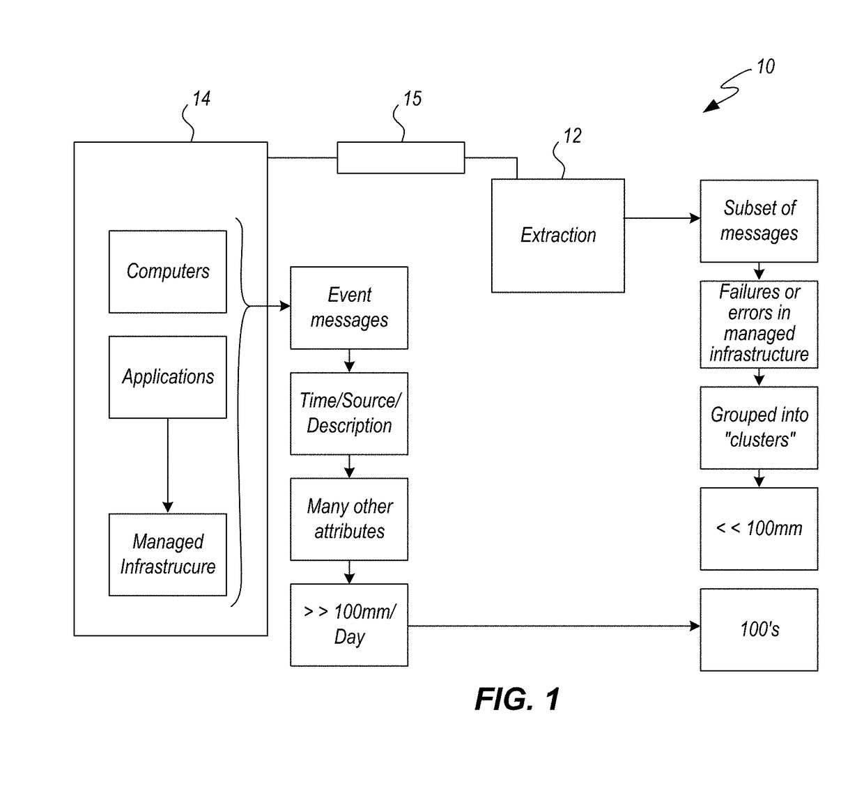
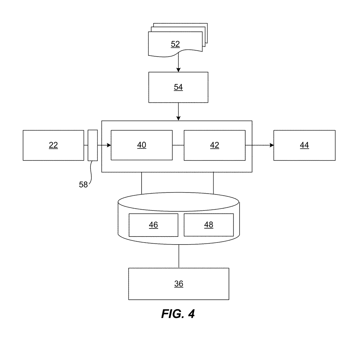
A system is provided for decomposing events from managed infrastructures. A first engine is configured to receive message data from a managed infrastructure that includes managed infrastructure physical hardware that supports the flow and processing of information, the at least one engine is configured to determine common characteristics of events and produce clusters of events relating to the failure of errors in the managed infrastructure. Membership in a cluster indicates a common factor of the events that is a failure or an actionable problem in a physical hardware of the managed infrastructure directed to supporting the flow and processing of information. The first engine is configured to create one or more situations that is a collection of one or more events or alerts representative of the actionable problem in the managed infrastructure. A second engine is configured to determine one or more common steps from events and produces clusters relating to events. The second engine determines one or more common characteristics of events and produces clusters of events relating to the failure or errors in the managed infrastructure. The system is configured to use data-driven fault localization, more particularly using semantic clustering.

Description

CROSS-REFERENCE TO RELATED APPLICATIONS[0001]This application claims the priority benefit of all of the following: U.S. Provisional Patent Application 62 / 612,438, filed on Dec. 30, 2017, U.S. Provisional Patent Application 62 / 612,435, filed on Dec. 30, 2017, U.S. Provisional Patent Application 62 / 612,437, filed on Dec. 30, 2017. This application is also a Continuation-In-Part of patent application Ser. No. 16 / 041,851, filed on Jul. 23, 2018, which is a Continuation-In-Part of patent application Ser. No. 16 / 041,792, filed on Jul. 22, 2018, which is a Continuation-In-Part of patent application Ser. No. 15 / 811,688, filed on Nov. 14, 2017, which is a Continuation-In-Part of patent application Ser. No. 15 / 810,297, filed on Nov. 13, which is a Continuation-In-Part of patent application Ser. No. 15 / 596,648, filed on May 16, 2017, which is a Continuation-In-Part of patent application Ser. No. 15 / 592,689, filed on May 11, 2017, which is a Continuation-In-Part of patent application Ser. No. 1...

Claims


Application Information

Patent Timeline
IPC IPC(8): H04L12/24H04L29/06H04L29/08H04L12/26G06F17/30
CPCH04L41/145H04L41/046H04L43/0823H04L67/42H04L41/142H04L41/12G06F16/951H04L63/029H04L67/34H04L43/067H04L41/0886H04L41/22H04L41/0893H04L43/10H04L41/064H04L41/065H04L63/0272H04L41/0894H04L67/01
Inventor TEE, PHILIPHARPER, ROBERT DUNCAN
Owner MOOGSOFT
Learn More