
Substrate processing device

Inactive Publication Date: 2019-01-31
ASM IP HLDG BV
View PDF0 Cites 232 Cited by
  • Summary
  • Abstract
  • Description
  • Claims
  • Application Information

AI Technical Summary

Benefits of technology

The patent text discusses devices that can address issues with distortion and substrate transfer in vacuum chambers with multiple reactors. The technical benefit of these devices is to improve the process of manufacturing semiconductor devices in vacuum environments.

Problems solved by technology

However, there is a limitation in reducing the processing time because a minimum amount of time is required to induce a reaction between the chemicals on the substrate.
However, there is a physical limit to reducing a reaction space because of the minimum space required for gas flow and exhaust.
However, in the case of the vacuum chamber having a plurality of reactors therein, as the size of the vacuum chamber increases, the weight of a chamber cover (top lid) constituting an upper portion of the chamber increases and the chamber cover is distorted by a vacuum force, which limits the number of reactors in the vacuum chamber.
Also, the degree of distortion of the chamber cover is increased in a high-temperature process.
However, in such a case, there is a problem that complexity of a chamber structure due to the addition of structures increases, and difficulty of operation / maintenance due to the increase in chamber weight increases.
In particular, as the size of a substrate increases, the physical size and volume of internal reactors to accommodate the substrate also increase correspondingly, which is a major obstacle to increasing the number of internal reactors and also limits the design and operation of a device.

Method used


Image

  • Substrate processing device
  • Substrate processing device
  • Substrate processing device

Examples


Embodiment Construction

[0036]Hereinafter, one or more example embodiments will be described more fully with reference to the accompanying drawings.

[0037]In this regard, the present example embodiments may have different forms and should not be construed as being limited to the descriptions set forth herein. Rather, these example embodiments are provided so that this disclosure will be thorough and complete, and will fully convey the scope of the inventive concept to one of ordinary skill in the art.

[0038]The terminology used herein is for the purpose of describing particular embodiments and is not intended to limit the inventive concept. As used herein, the singular forms “a,”“an” and “the” are intended to include the plural forms as well, unless the context clearly indicates otherwise. It will be further understood that the terms “includes,”“comprises” and / or “including,”“comprising” used herein specify the presence of stated features, integers, steps, operations, members, components, and / or groups there...


PUM


Abstract

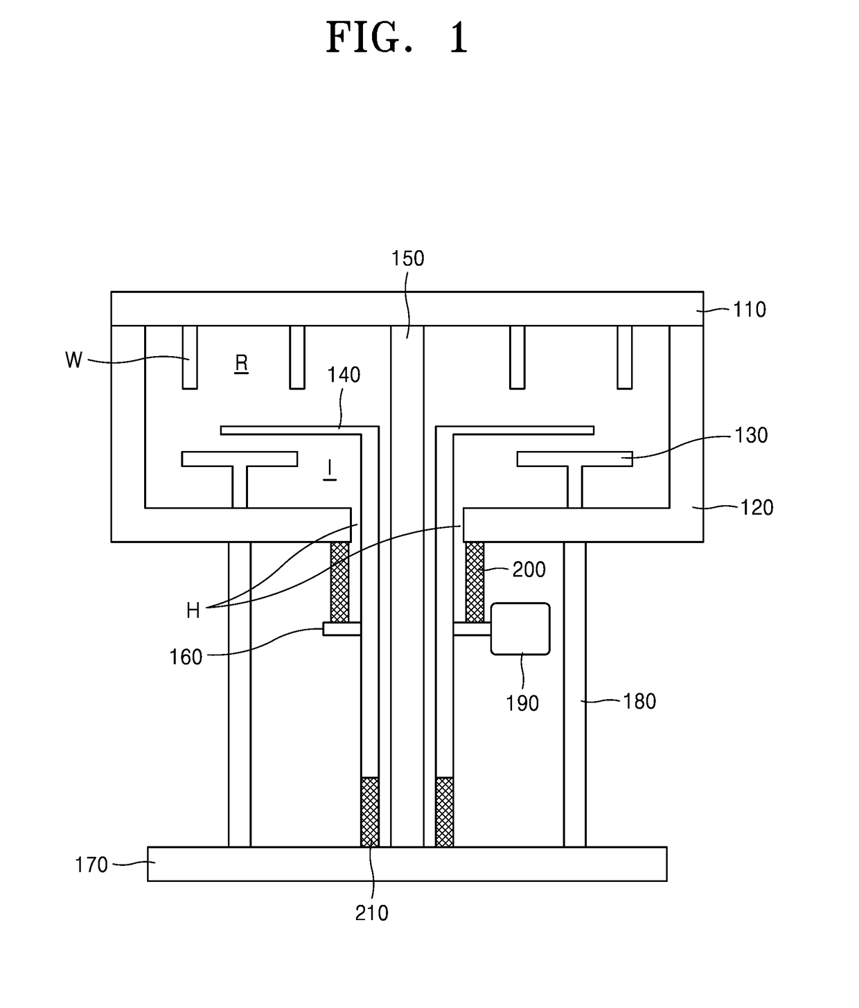
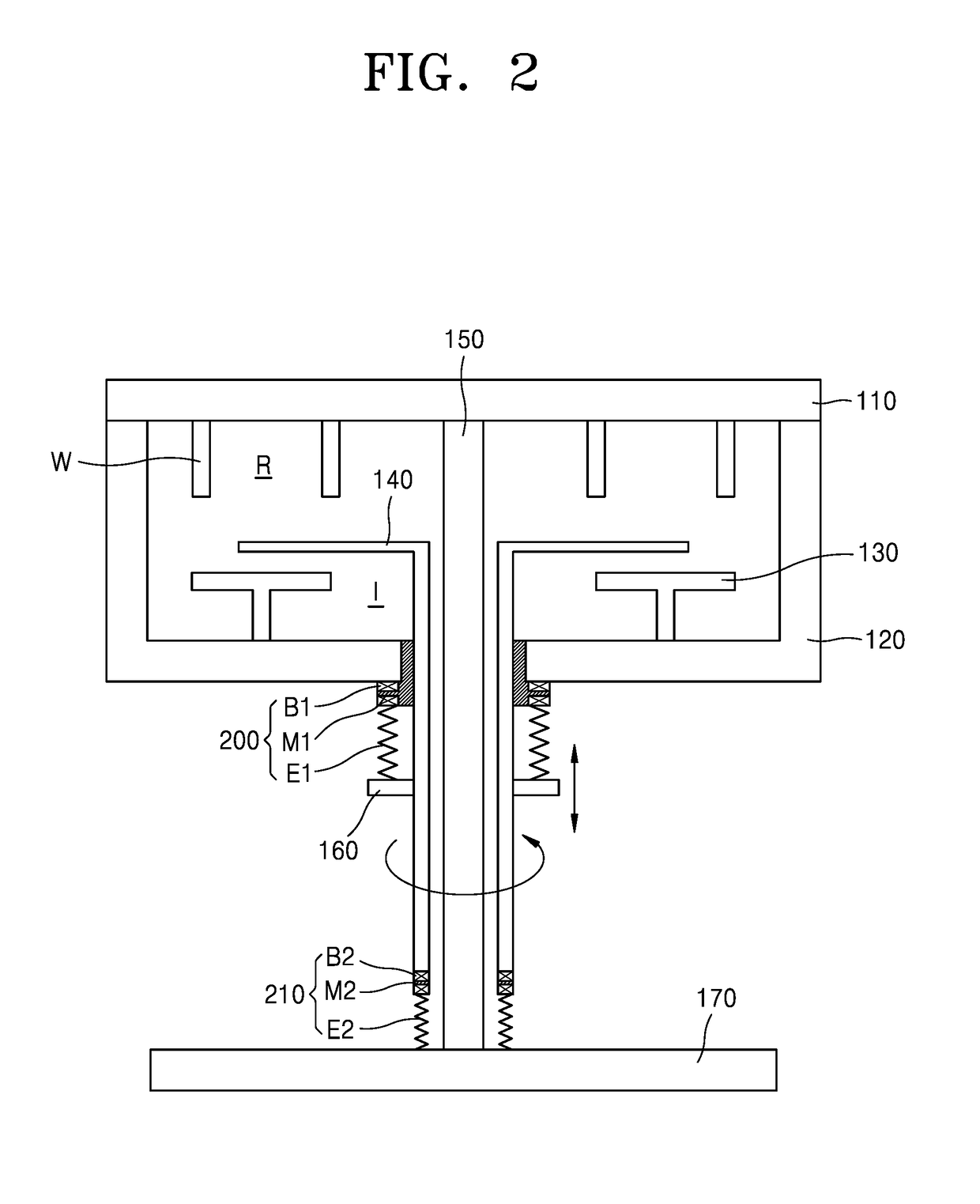
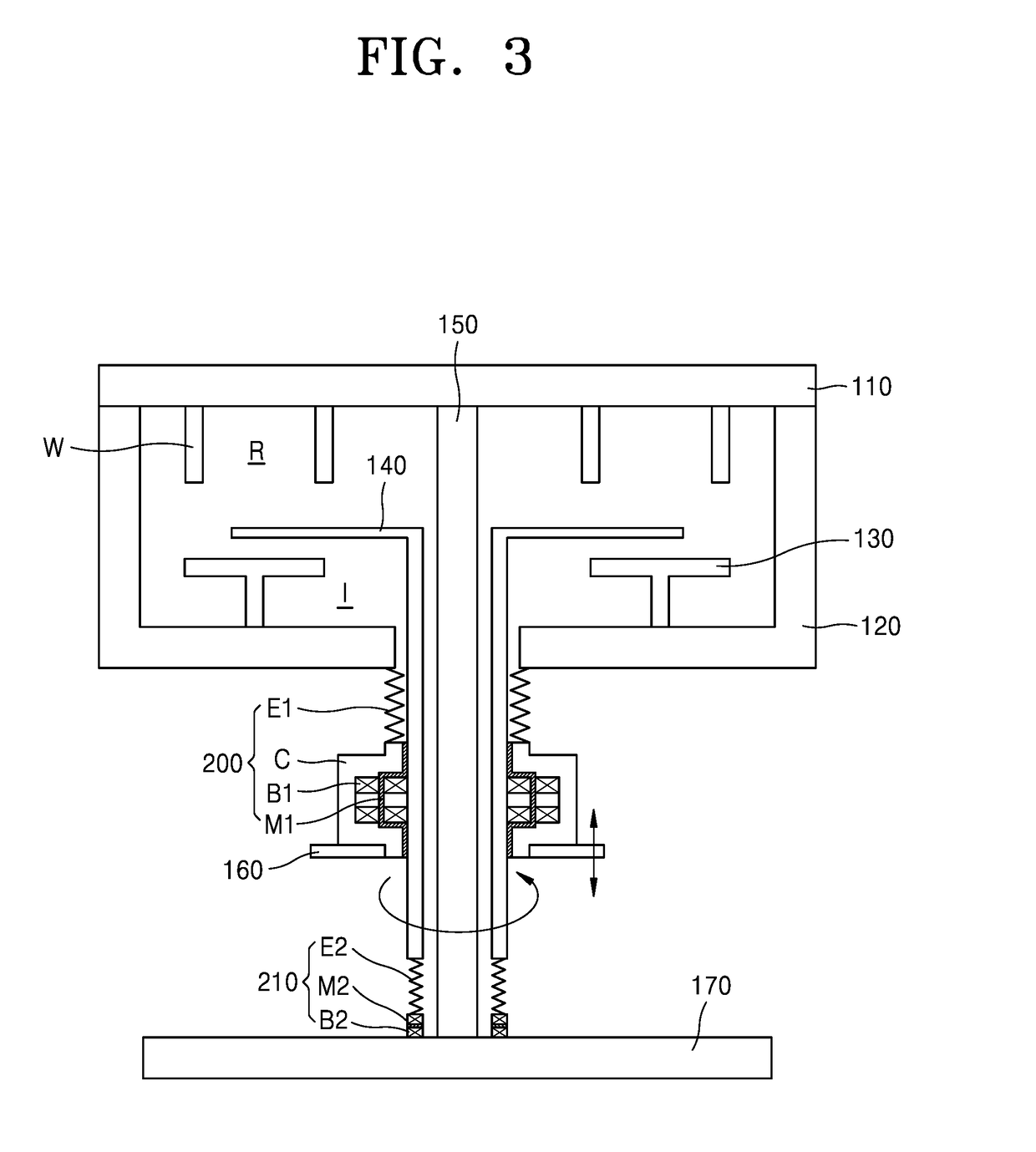
Provided is a substrate-processing device capable of preventing a top lid from sagging downward by the own weight of the substrate-processing device and / or a vacuum suction force generated by a vacuum pump and / or thermal shock at high temperature process, in a chamber including a plurality of reactors. Also, provided is a rotating shaft for transferring a substrate between the plurality of reactors.

Description

CROSS-REFERENCE TO RELATED APPLICATION[0001]This application claims the benefit of Korean Patent Application No. 10-2017-0097136, filed on Jul. 31, 2017, in the Korean Intellectual Property Office, the disclosure of which is incorporated herein in its entirety by reference.BACKGROUND1. Field[0002]One or more example embodiments relate to a substrate-processing device, and more particularly, to a substrate-processing device capable of preventing sagging or deformation of a top lid.2. Description of the Related Art[0003]Recently, many attempts have been made to increase productivity (the number of substrates that can be processed per unit time) in semiconductor manufacturing. For example, there is a method of reducing a processing time for treating chemicals on a substrate. However, there is a limitation in reducing the processing time because a minimum amount of time is required to induce a reaction between the chemicals on the substrate.[0004]Another method is to develop a reactor o...

Claims


Application Information

Patent Timeline
IPC IPC(8): H01L21/67
CPCH01L21/67023H01L21/67126H01L21/67098H01L21/6719H01L21/68742H01L21/68771H01L21/68792H01L21/67201H01L21/683
Inventor LEE, JU ILKIM, HIE CHULKIM, DAE YOUN
Owner ASM IP HLDG BV
Learn More