
Method for adjusting time stamps during the acquisition of sensor data

Active Publication Date: 2019-01-24
ROBERT BOSCH GMBH
View PDF4 Cites 0 Cited by
  • Summary
  • Abstract
  • Description
  • Claims
  • Application Information

AI Technical Summary

Benefits of technology

The present invention relates to detecting irregularities in communication events. By measuring the duration of a communication link, and comparing it to a reference value, it can determine if there is any deviation from the expected pattern. This way, small fluctuations in the duration of a communication link can be ignored, reducing correction and computing expenditure. The invention also helps suppress natural fluctuations and irregularities in the systems, such as background noise.

Problems solved by technology

Since, in principle, both sensor systems and the host system may be faulty, different time bases are produced for the specific systems.

Method used


Image

  • Method for adjusting time stamps during the acquisition of sensor data
  • Method for adjusting time stamps during the acquisition of sensor data
  • Method for adjusting time stamps during the acquisition of sensor data

Examples


Embodiment Construction

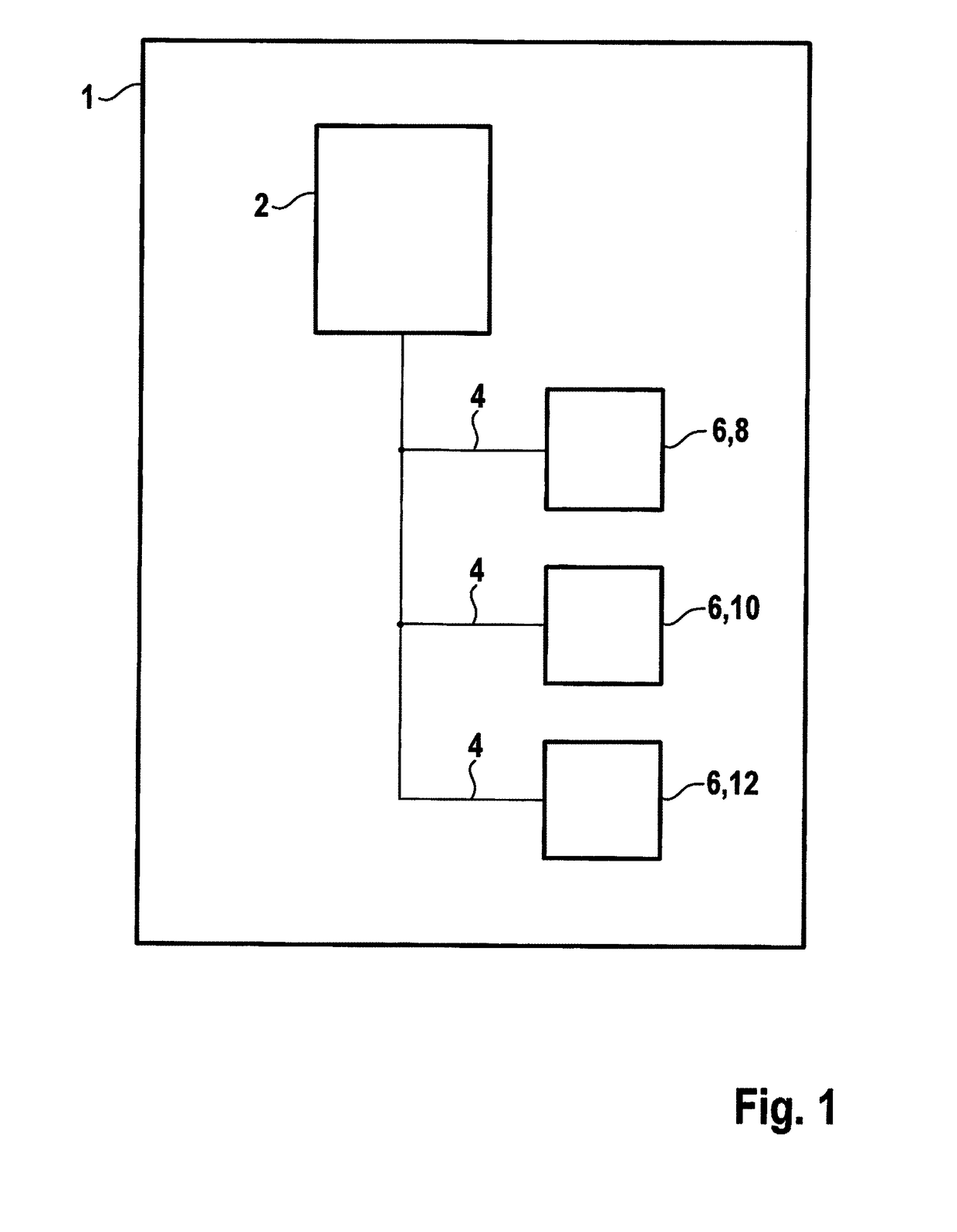
[0024]FIG. 1 shows a schematic representation of a device 1 according to a first exemplary embodiment. Device 1 includes a host system 2 in the form of an application processor 2. Host system 2 is connected to a plurality of sensor systems 6 via a plurality of communication links 4. According to the exemplary embodiment, sensor systems 6 include a temperature sensor 6, 8, an acceleration sensor 6, 10 and a brightness sensor 6, 12.

[0025]Measured sensor data 14 from sensor systems 6 are retrieved by host system 2 in regular time intervals 16, via communication links 4.

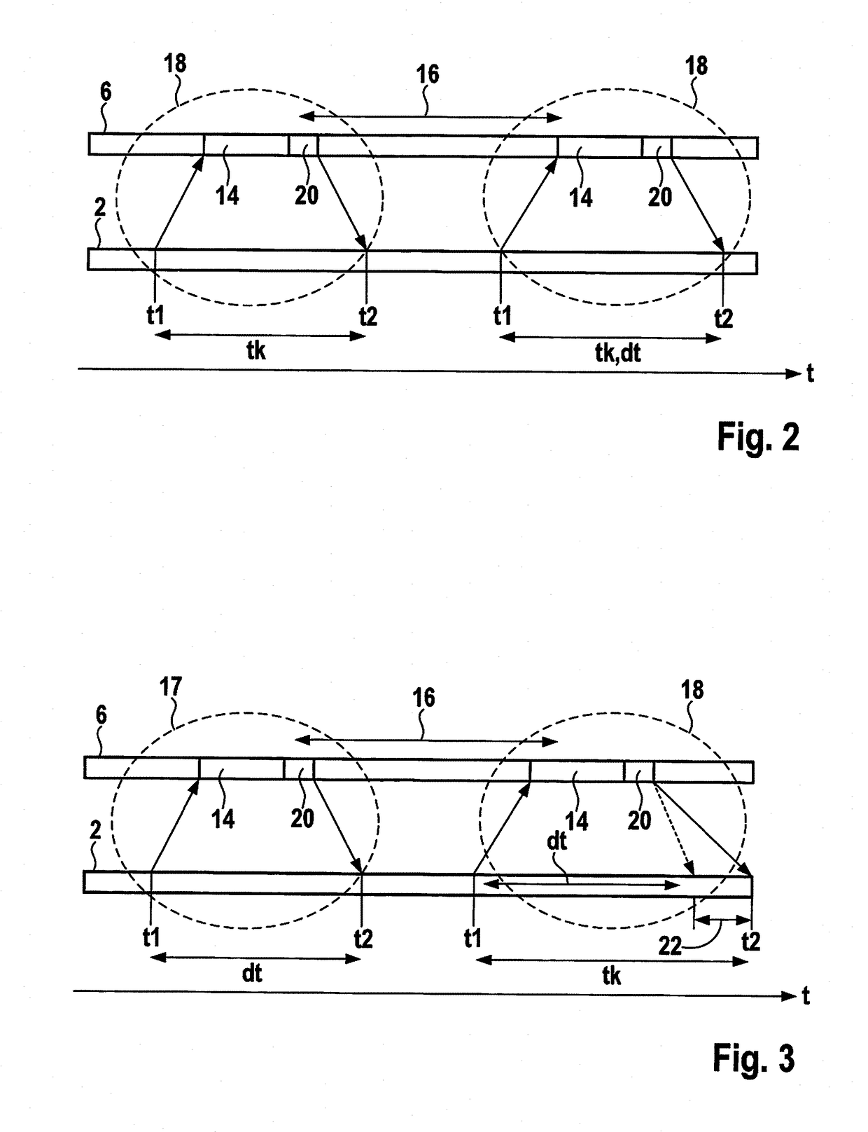
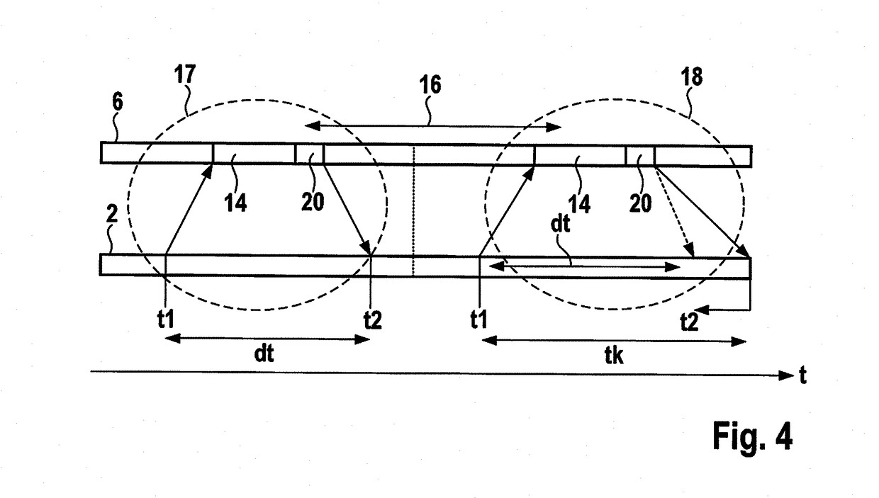
[0026]A schematic time sequence of two communication events 18 is represented in FIG. 2. In this connection, a time axis of sensor system 6 and a time axis of host system 2 are shown. In regular time intervals 16, host system 2 initiates communication events 18 for retrieving sensor data 14. In this case, sensor data 14 are, for example, measured temperature values. In addition to sensor data 14, temporal information 20 ...


PUM


Abstract

A method for synchronizing sensor data of a sensor system with the host time base of a host system, based on the clock ratio of the sensor time base to the host time base. To ascertain the clock ratio for at least two communication events, a time stamp acquisition is performed for each event, in which a sensor time stamp and a host time stamp is recorded. The communication events for ascertaining the clock ratio relate to a specific quantity of data. The ratio is ascertained / updated repeatedly; the duration of the individual communication events for the time stamp acquisition are measured; and by comparing each measured duration to a comparison value, possible irregularities in the communication event are detected. The host time stamp of a time stamp acquisition is corrected / replaced by a calculated host time stamp based on the measured irregularities. Also described is a related device for the method.

Description

RELATED APPLICATION INFORMATION[0001]The present application claims priority to and the benefit of German patent application no. 10 2017 212 353.2, which was filed in Germany on Jul. 19, 2017, the disclosure which is incorporated herein by reference.FIELD OF THE INVENTION[0002]The present invention relates to a device and a method for adjusting time stamps during the acquisition of sensor data.BACKGROUND INFORMATION[0003]Measured sensor data of different sensor systems, such as inertial, camera and acoustic sensors, are provided with time stamps, in order to be able to selectively link and process the measurement data. The different sensor systems are normally operated by different, respective, internal clock generators. Therefore, there is no synchronism between the sensor systems. Each system may operate with different accuracy and at a frequency variable over time. In particular, if the sensor data on the specific sensor system are collected in a FIFO (first input first output) d...

Claims


Application Information

Patent Timeline
IPC IPC(8): H04L7/00H04L7/04H04L7/08
CPCH04J3/0661H04J3/0638H04L12/40H04Q9/00H04Q2209/753H04L7/0012H04L7/0037H04L7/042H04L7/08
Inventor HAUBELT, CHRISTIANDORSCH, RAINERSTIEBER, SEBASTIANLIU, SHENGXIAN
Owner ROBERT BOSCH GMBH
Learn More