CMOS image sensor on-die motion detection using inter-pixel mesh relationship

a technology of inter-pixel mesh relationship and image sensor, which is applied in image analysis, instruments, computing, etc., can solve the problems of short battery life per charge cycle and high power consumption of computing devices, and achieve the effect of relatively small memory space for storing inter-pixel mesh relationship information and power consumption

Active Publication Date: 2019-01-24
QUALCOMM INC
View PDF3 Cites 5 Cited by
  • Summary
  • Abstract
  • Description
  • Claims
  • Application Information

AI Technical Summary

Benefits of technology

[0003]This disclosure generally relates to image sensors for motion detection and / or tracking. More specifically, techniques disclosed herein relate to a complementary metal-oxide-semiconductor (CMOS) image sensor that can generate inter-pixel mesh relationship information for motion detection, where changes in inter-pixel mesh relationship may indicate motions of objects in the field of view of the CMOS image sensor and the relevant location of the object in motion. Thus in at least one embodiment, no analog-to-digital conversion (ADC) circuit is required to convert analog sensor signals to digital data for motion detection. In at least one embodiment, no analog memory is used to store analog sensor signals in the pixel level. The memory space for storing the inter-pixel mesh relationship information can be relatively small. The power consumption of the image sensor using the techniques disclosed herein can be much lower than the power consumption exhibited in conventional techniques, such as an image sensor with a pixel array and an ADC interface, in conjunction with software-based or hardware-based (e.g., digital signal processing (DSP) hardware-based) motion detection technique.

Problems solved by technology

Capturing images in the field of view of the computing device using traditional image sensors and processing the captured images to detect motions using conventional processors require significant processing resources, resulting in high power consumption and short battery life per charge cycle in computing devices, which may be very sensitive to power consumption.

Method used


Image

  • CMOS image sensor on-die motion detection using inter-pixel mesh relationship
  • CMOS image sensor on-die motion detection using inter-pixel mesh relationship
  • CMOS image sensor on-die motion detection using inter-pixel mesh relationship

Examples


Embodiment Construction

[0034]Several illustrative embodiments will now be described with respect to the accompanying drawings, which form a part hereof. While particular embodiments, in which one or more aspects of the disclosure may be implemented, are described below, other embodiments may be used and various modifications may be made without departing from the scope of the disclosure or the spirit of the appended claims.

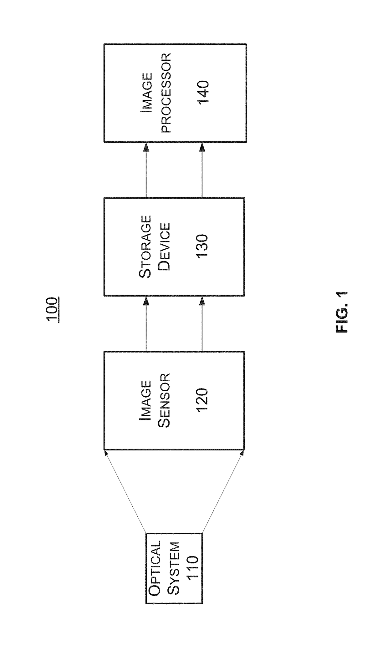
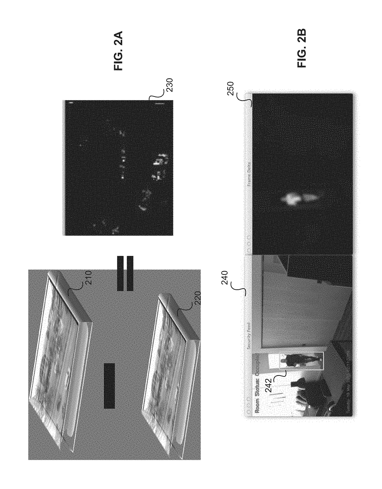
[0035]The present disclosure generally relates to motion sensing, detection, and / or tracking using image sensors. Motion sensing, detection, and / or tracking may be used in various devices for various applications, such as, for example, security and autonomous driving. For remote motion sensing, an image sensor may be used to capture image frames for a remote scene, and detect motions based on the temporal differences between different image frames. In, for example, various power sensitive or bandwidth sensitive devices and applications, motion sensing and detection may be used to trigge...


PUM


Abstract

Techniques for motion detection are presented. An image sensor for motion detection includes a plurality of analog comparators and a two-dimensional pixel array including a plurality of rows of pixels and a plurality of columns of pixels. Each pixel is configured to convert an optical signal on the pixel into an analog signal. The two-dimensional pixel array is organized into a plurality of groups of pixels each associated with a combined group signal determined based on the analog signals from pixels in the group of pixels. Each analog comparator includes two inputs and is used to compare combined group signals generated by two groups of pixels of the plurality of groups of pixels during a same time period to generate a 1-bit inter-pixel digital signal, where each of the two groups of pixels is coupled to a corresponding input of the two inputs of the each analog comparator.

Description

BACKGROUND[0001]Computer vision involves acquiring, processing, analyzing, and understanding images for use in various applications. Traditionally, an image processor (e.g., an image sensor processor) coupled to an image sensor may acquire image data from the image sensor and perform certain computer vision operations on the acquired image data to detect features in the image data and / or changes among different frames in the image data. The detected features and / or changes may be used in a variety of applications, such as object classification, face recognition, motion detection, object / feature tracking, gesture detection, etc.[0002]Much effort has been made in recent years to enable computing devices to detect motions in the field of view of a computing device, such as a mobile device. Capturing images in the field of view of the computing device using traditional image sensors and processing the captured images to detect motions using conventional processors require significant pr...

Claims


Application Information

Patent Timeline
Patent Type & Authority Applications(United States)
IPC IPC(8): G06T7/20G06K9/46G06K9/00G06K9/32G06K9/62G06T7/70
CPCH04N25/40H04N25/76H04N25/75G06V20/64G06T7/70G06T7/20
Inventor FU, ZHENGMINGYAO, JIATAYEBI, DAROOSH
Owner QUALCOMM INC
Why Eureka
Try Eureka