
Vacuum deposition device for high-speed coating

a vacuum deposition and coating technology, applied in the direction of reversed direction vortex, vortex flow apparatus, separation process, etc., can solve the problems of low energy efficiency, degrading quality, and almost impossible to coat high melting point materials such as titanium, chrome, etc., and achieve high coating uniformity

Inactive Publication Date: 2019-01-17
POHANG IRON & STEEL CO LTD
View PDF10 Cites 0 Cited by
  • Summary
  • Abstract
  • Description
  • Claims
  • Application Information

AI Technical Summary

Benefits of technology

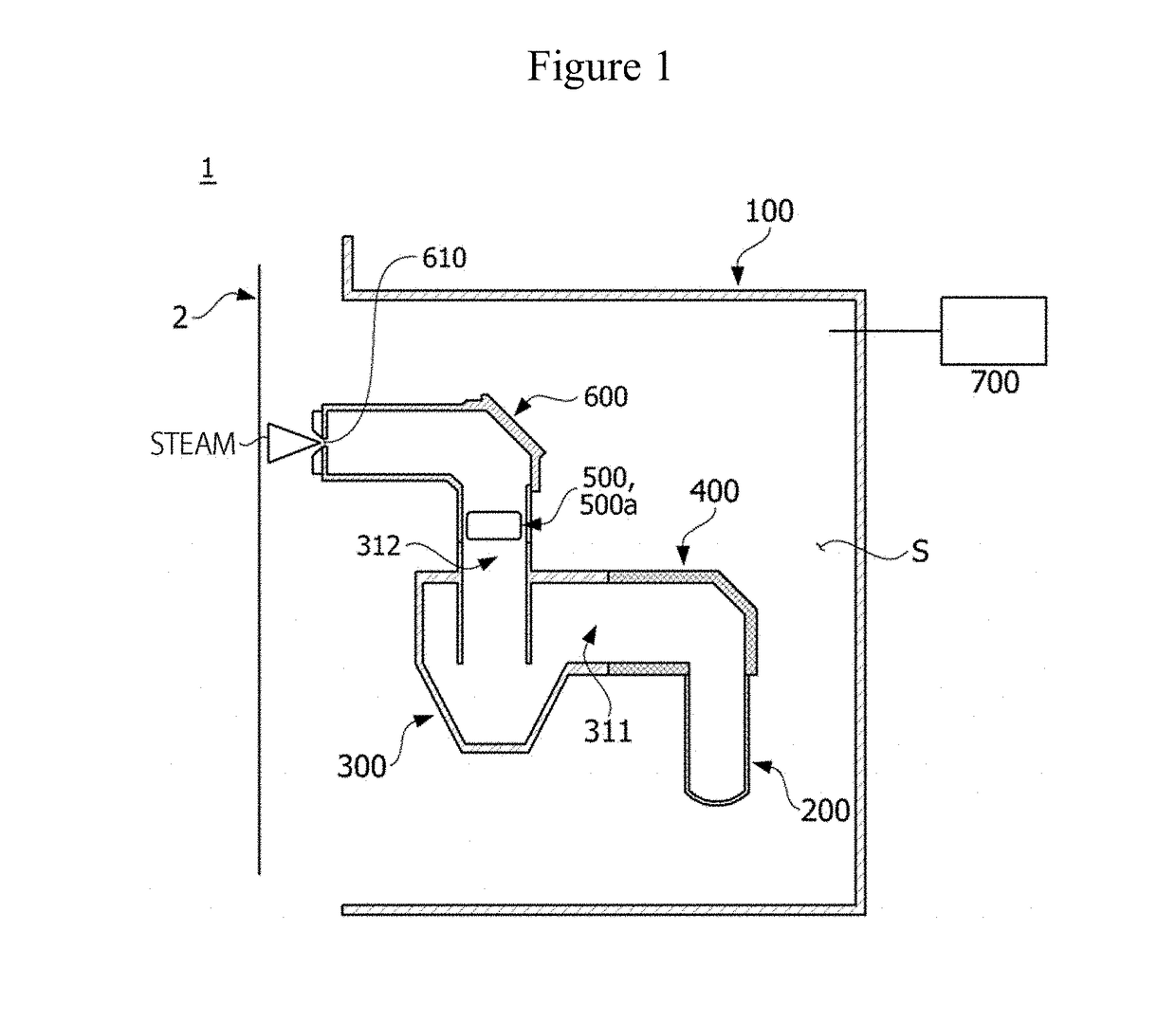
The present invention is about a vacuum deposition device for high-speed coating. This device has several technical effects. Firstly, it uses a cyclone filter to remove coarse particles during coating, which improves the quality of the coating. Secondly, it prevents the rotation of steam by using a baffle, which results in a more uniform coating. Overall, this device helps achieve high-speed, high-quality coating.

Problems solved by technology

Since the method is limited to heating of a coating material by resistive heating, it is almost impossible to coat a high melting point material such as titanium, chrome or the like.
However, there is a disadvantage of low energy efficiency due to heat loss caused by a contact between the evaporated material and the crucible.
However, when the temperature of the coating material excessively increases due to the increase in the power, coarse particles are discharged from a mass of the coating material due to an effect of simultaneous evaporation and boiling, and a specimen is coated with the coarse particles, thus quality is degraded.
That is, heating power of the coating material should increase so that high speed coating is performed, but the high speed coating has limitations due to the coarse particles that degrade the quality of coating.
The technology can prevent boiling of coarse particles generated during deposition but is inadequate to technology of removing coarse particles at a level applicable to high speed coating.
That is, heating power of the coating material should increase to perform high speed coating, but it is practically difficult to perform the high speed coating while a temperature of a surface of the coating material is maintained at high temperatures while an interior temperature of the coating material is maintained under a boiling point by the technology of preventing boiling of the coating material.
However, there is a problem in which coarse particles generated due to boiling of the coating material cannot be removed.
Particularly, in the case of the high speed coating, most coarse particles are generated due to boiling of a coating material, and thus the technology has limitations in application of high speed coating.
In the technology of inserting a member blocking a coarse particle, a blocking member is used to block steam, and thus there is a problem in which a coating speed is sharply lowered.
Further, the blocking member has a problem of functioning as a medium generating coarse particles.

Method used


Image

  • Vacuum deposition device for high-speed coating
  • Vacuum deposition device for high-speed coating
  • Vacuum deposition device for high-speed coating

Examples


Embodiment Construction

[0042]While the present invention is susceptible to various modifications and alternative forms, specific embodiments thereof are shown by way of example in the drawings and will herein be described in detail. It should be understood, however, that there is no intent to limit the present invention to the particular forms disclosed, but on the contrary, the present invention is to cover all modifications, equivalents, and alternatives falling within the spirit and scope of the present invention.

[0043]It will be understood that, although the terms “first,”“second,” etc. may be used herein to describe various elements, the elements should not be limited by the terms. These terms are only used to distinguish one element from another. For example, a first element could be termed a second element, and similarly, a second element could be also termed a first element, without departing from the scope of the present invention. As used herein, the term “and / or” includes any and all combinatio...


PUM

PropertyMeasurementUnit
diameteraaaaaaaaaa
diameteraaaaaaaaaa
particle diameteraaaaaaaaaa

Abstract

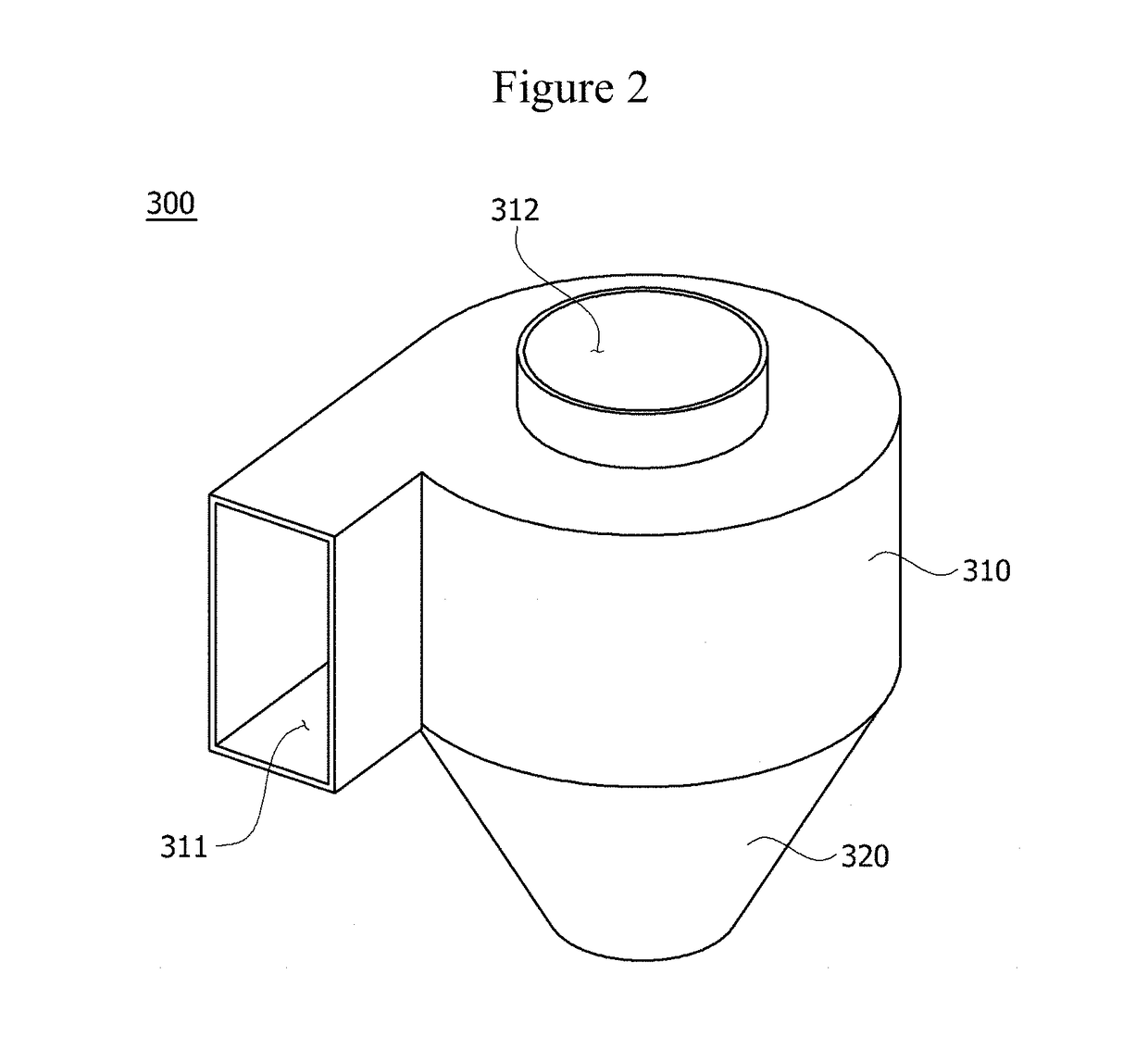
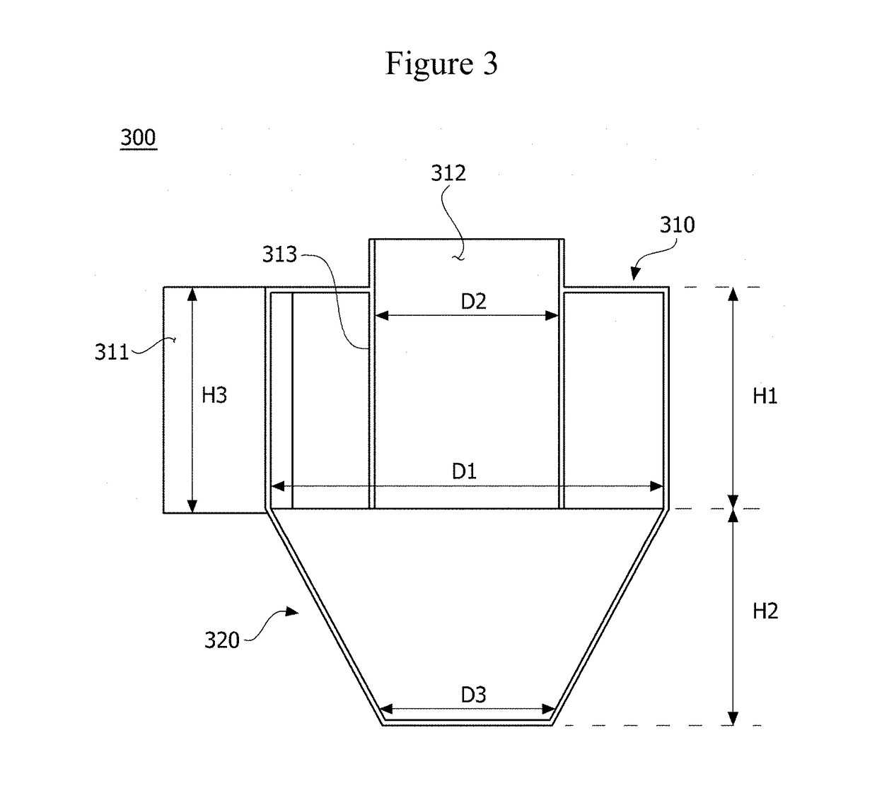
Provided is a vacuum deposition device for high-speed coating, comprising: a vacuum chamber having a reception space arranged therein; an evaporation crucible disposed in the reception space to evaporate a coating material; and a cyclone filter disposed in the reception space, wherein the cyclone filter separates a coarse particle from steam generated during the evaporation of the coating material. Therefore, the vacuum deposition device for high-speed coating can remove a coarse particle generated in the high-speed coating, prevent the rotation of steam, using a baffle inserted between a steam ejection opening and an exit of the cyclone filter, and thus obtain a coating layer having the excellent uniformity of coating.

Description

TECHNICAL FIELD[0001]The present invention relates to a vacuum deposition device for high-speed coating, and more specifically, to a vacuum deposition device for high-speed coating which removes coarse particles generated during high-speed coating.BACKGROUND ART[0002]Vacuum deposition is a technology of forming a thin film by heating and evaporating a solid coating material by various methods under a vacuum condition to be changed into steam and spraying the steam to a plating target object, and a coating method is mainly classified according to a heating method.[0003]Typical vacuum deposition methods include a thermal evaporation method, an electron beam evaporation method, and an electro-magnetic levitation evaporation method.[0004]The thermal evaporation method is a method of coating a substrate by heating and evaporating a solid coating material, which is put in a filament, a boat, or a crucible made of metal, ceramic, or graphite, by resistive heating. Since the method is limit...

Claims


Application Information

Patent Timeline
Patent Type & Authority Applications(United States)
IPC IPC(8): B04C5/103B01D45/16C23C14/24
CPCB04C5/103C23C14/26C23C14/243B01D45/16
Inventor NAM, KYUNG HOONKIM, SANG JOONKO, KYOUNG PILKIM, TAE YEOBEOM, MUN JONG
Owner POHANG IRON & STEEL CO LTD
Learn More