
Multi Oriented, Power Source Agnostic Replacement For Lighting Assembly

a technology of power source and lighting assembly, applied in the direction of light source, electric lighting, lighting and heating apparatus, etc., can solve the problems of mercury release, health danger, photosensitive epilepsy, etc., and achieve the effect of reducing hot spots and dark areas

Active Publication Date: 2019-01-03
SIGNLIGHTSLED LLC
View PDF0 Cites 2 Cited by
  • Summary
  • Abstract
  • Description
  • Claims
  • Application Information

AI Technical Summary

Benefits of technology

This patent is about a lighting system that can replace existing signs and lights. It includes a support structure, LED strips, and connectors for attaching the LED strips and an external power supply. Different lighting assemblies can be connected together to create a lighting system that reduces hot spots and dark areas. The technical effects of this invention include an improved lighting system that is more efficient and better-controlled, as well as a more compact and customizable system that can be used in different signs and displays.

Problems solved by technology

Because each lamp is an enclosed tube typically containing mercury, breaking the tube can release the mercury creating a health danger.
There is also evidence that flickering from fluorescent lamps can cause seizures in patients with photosensitive epilepsy, but there has yet to be any evidence to date attributing seizures to compact fluorescent lamps.
However, these solutions require that the ballast of the fluorescent assembly remain in the structure.
Further, the use of LED lighting is typically done with a LED lighting strip thereby making lighting requirements needing two-sided light projection difficult.
This results in a situation where the electrician or other individual tasked with installing new lights, repairing lights or signs, replacing lights, or upgrading lights has to first determine the power in, the proper wires to use in a sign housing, and which wires to connect to the new lighting assembly.
This task takes time and can result in increased chance of electrical wiring mistakes.
Further, there is no standard wiring configuration for sign housings so that the power supply could be located about anywhere within the sign housing from the external power source.
This housing design does not allow for changing the location or the number of lighting assembly in a housing without rewiring the housing itself.
This technology is on the decline, but nevertheless millions of tubes still exist.
The resulting disadvantage is that the majority of the installed T12 lamps are 8 feet in length, making it troublesome and even dangerous to store, handle and manipulate the T12 lamp or even the T8 lamp as this 8-foot length.
For example, the standard door is 80 inches in height or 6 feet 8 inches making manipulating an 8-foot lamp through a door challenging.
When a fluorescent lamp is broken, such as the eight-foot T12, there are health risks due to the use of mercury that can exist in vapor and a solid upon breakage.
In fact, one study shows that it would take over 20 minutes in a fan ventilated room for the mercury released from a broken fluorescent tube to dissipate to normal levels.
PCBs are contained within the fluorescent light ballast's capacitors and interior potting material of older magnetic T12 lighting fixtures causing them to be hazardous to human health.
Additionally, intact PCB-containing fluorescent light ballasts may emit small amounts of PCBs into the air during normal use of the lighting fixtures.
Additionally, Department of Energy regulations have virtually eliminated the new installation of T12 technology so that replacement parts of these existing lighting system as becoming increasingly hard to come by.
This reduction in supply has led to increased costs of replacement parts.
The result of these health risks, regulatory pressures and financial disincentives is that lighting system has been replaced to eliminate these older systems.
However, none of these attempts solve the problems with reducing the length of the lamp below 8 feet and improving performance, using the existing reflector and housing and existing power supply.
The disadvantages are due, in part, to the operation of lamps at the customary power frequency of 50 or 60 Hz causing the lights to flicker at these frequencies resulting in stroboscopic effects.

Method used


Image

  • Multi Oriented, Power Source Agnostic Replacement For Lighting Assembly
  • Multi Oriented, Power Source Agnostic Replacement For Lighting Assembly
  • Multi Oriented, Power Source Agnostic Replacement For Lighting Assembly

Examples


Embodiment Construction

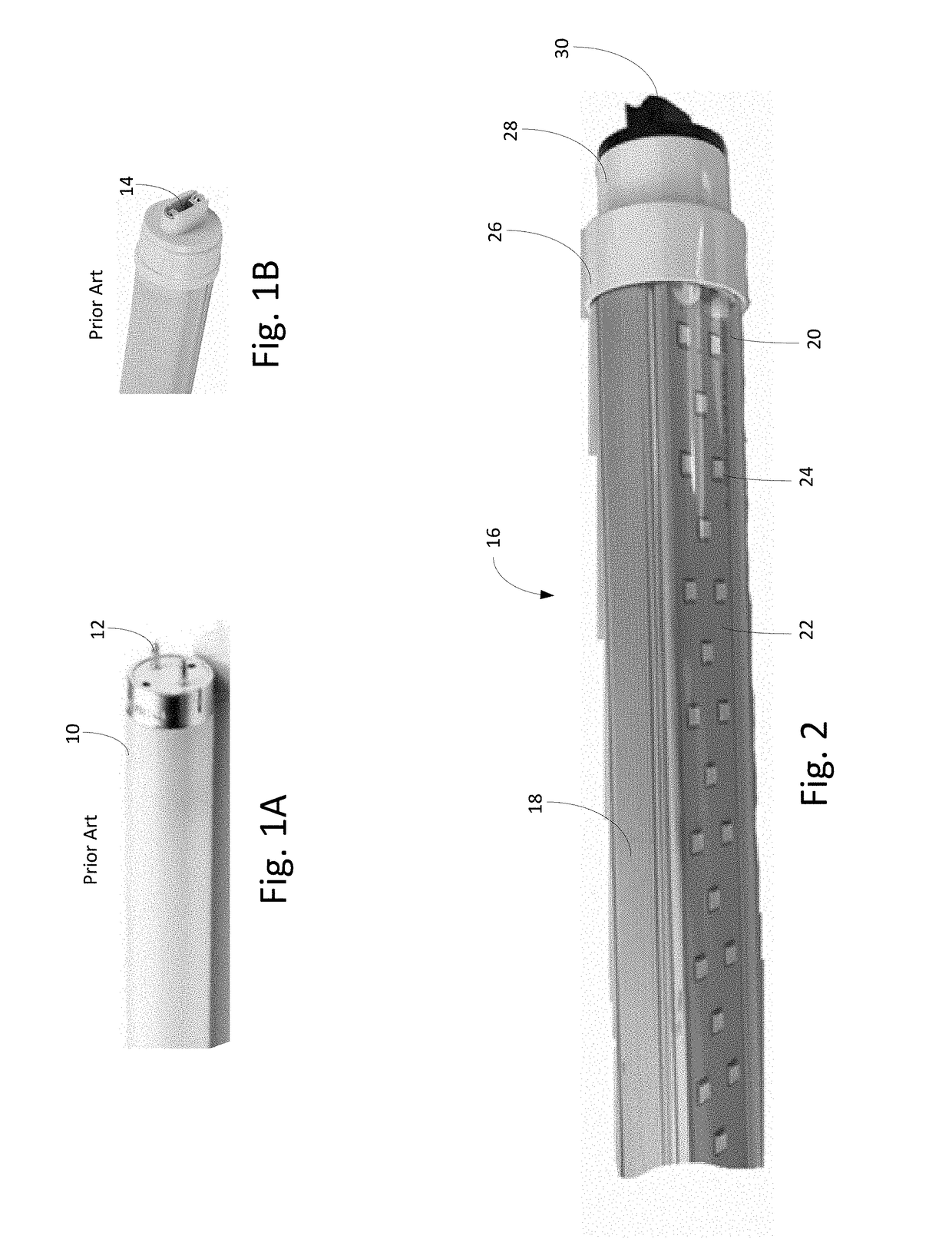
[0051]With reference to the drawings, the invention will now be described in more detail. Referring to FIG. 1A, a traditional fluorescent lamp 10 is shown having pin connectors 12. These pin connectors are received into a socket securing the fluorescent tube into a light fixture. The light generated can project generally 360° from the long axis of the tube. With this tube, the fluorescent tube can be used with a reflector to restrict the light production and can be used with an application needing 360° such as with illuminated signs. FIG. 1B illustrates another end connector 14 with recessed pins providing for electrical contact for the fluorescent tube.

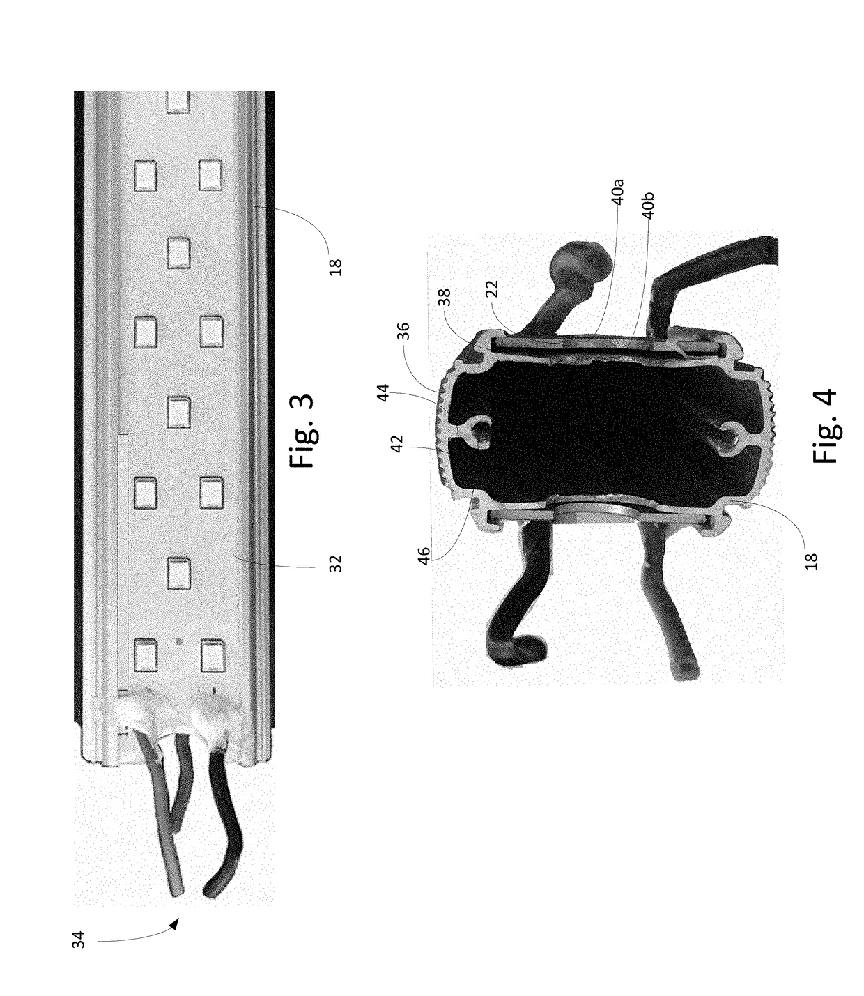
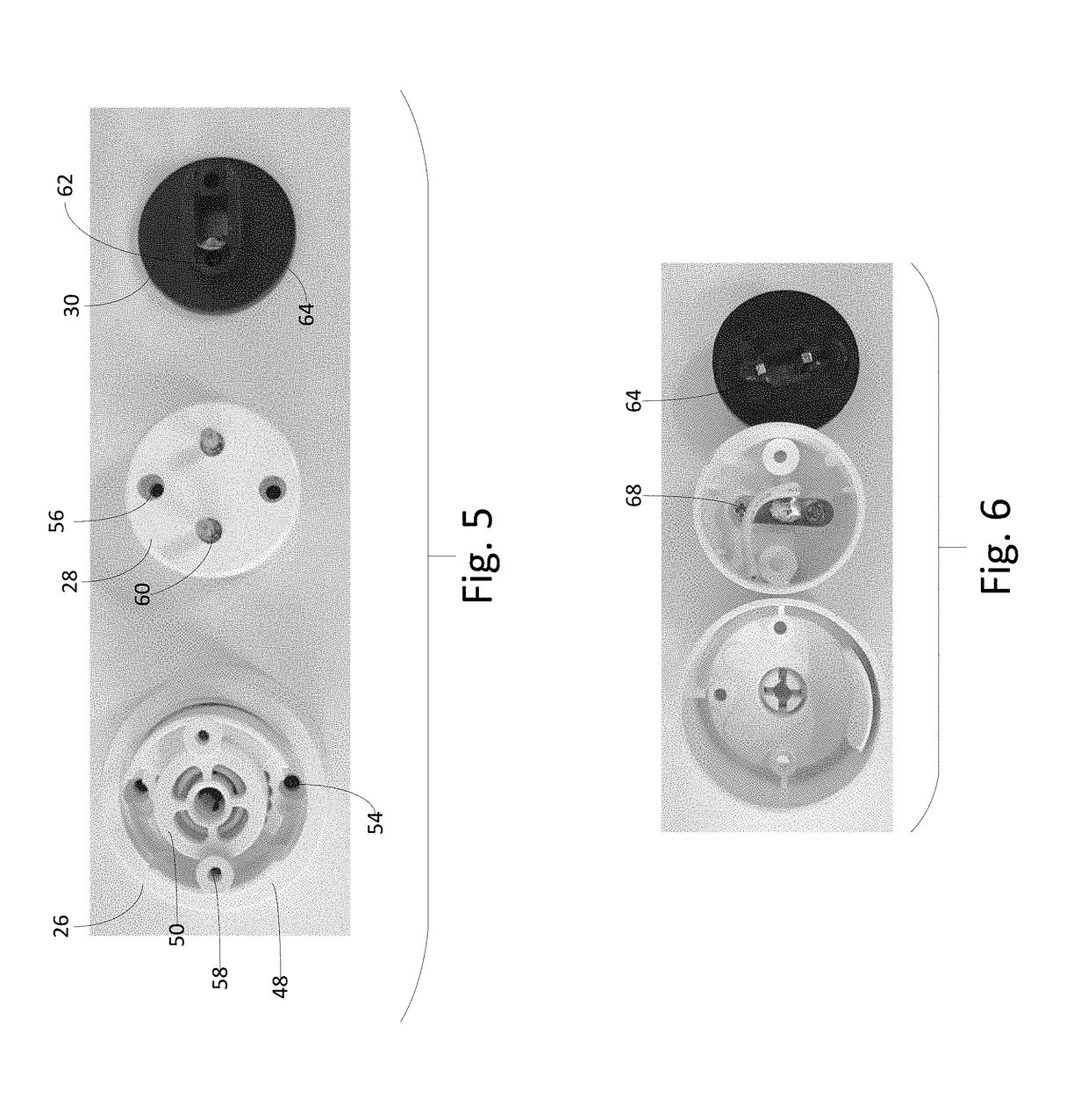
[0052]Referring to FIG. 2, a lighting assembly 16 is shown having a support structure 18 that can have attached to it a clear cover 20 that can cover a LED strip 22. The LED strip can include individual LED lamps 24 that can be arranged in a linear fashion, in a single, or a multiple row configuration and can be in an offset configur...


PUM


Abstract

This invention is a replacement lighting system for signs that can include a first lighting assembly having LED strips disposed on opposite sides. The lighting assembly can be rotatably attached to the lamp holders. A hub can be removably connected to an external power supply, a first lighting assembly and a second lighting assembly. The lighting system can be used to replace existing lighting such as fluorescent tubes and accompanying ballasts without the need to understand remove or rewire the sign electrical components other than attaching the lighting system to the power source. The lighting assemblies can be rotated in the lamp holders to reduce or remove hot spots or dark areas. Multiple lighting assemblies can be connected end to end and be in electrical communication with the power source without necessarily needing to wire each lighting assembly to the power source.

Description

BACKGROUND OF THE INVENTION1) Field of the Invention[0001]This invention is directed to a power source agnostic replacement for a lighting assembly tube that can be used to replace traditional fluorescent lighting such as in commercial signs.2) Description of Related Art[0002]A fluorescent lamp, well known in the art, is typically a low-pressure mercury-vapor gas-discharge lamp that uses fluorescence to produce visible light. The lamp is constructed by providing a tube filled with a gas containing low pressure mercury vapor and argon, xenon, neon, or krypton. An electrical current excites vapor which results in a short-wave ultraviolet light. This UV light causes a phosphor coating on the inside of the lamp to glow providing light. Fluorescent lamp tubes are typically straight, have a rounded cross section, and have a length in the range of about 4 inches to about 8 feet. Because each lamp is an enclosed tube typically containing mercury, breaking the tube can release the mercury cr...

Claims


Application Information

Patent Timeline
Patent Type & Authority Applications(United States)
IPC IPC(8): F21K9/278F21K9/272
CPCF21K9/278F21K9/272F21Y2115/10F21Y2103/10F21S2/00Y02B20/30
Inventor POWELL, AUSTIN MCCOYPATEL, ISHAVARBHALHANVEY, JIMMY
Owner SIGNLIGHTSLED LLC
Learn More