
Securing device for GIS

a technology of gis and gis contact, which is applied in the direction of coupling device connection, total enclosed bus-bar installation, coupling contact member, etc., can solve the problem of limiting assembly errors on site, and achieve the effect of reducing hot spots in gis and limiting electrical resistan

Inactive Publication Date: 2017-01-03
ALSTOM TECH LTD
View PDF8 Cites 0 Cited by
  • Summary
  • Abstract
  • Description
  • Claims
  • Application Information

AI Technical Summary

Benefits of technology

The solution significantly reduces on-site assembly time and errors, enhances electrical conductivity by minimizing hot spots, and ensures gastightness, allowing for efficient assembly of sub-modules remotely and final assembly with improved mechanical stability and reduced leak rates.

Problems solved by technology

Pre-assembly also limits on-site assembly errors.

Method used


Image

  • Securing device for GIS
  • Securing device for GIS
  • Securing device for GIS

Examples


Embodiment Construction

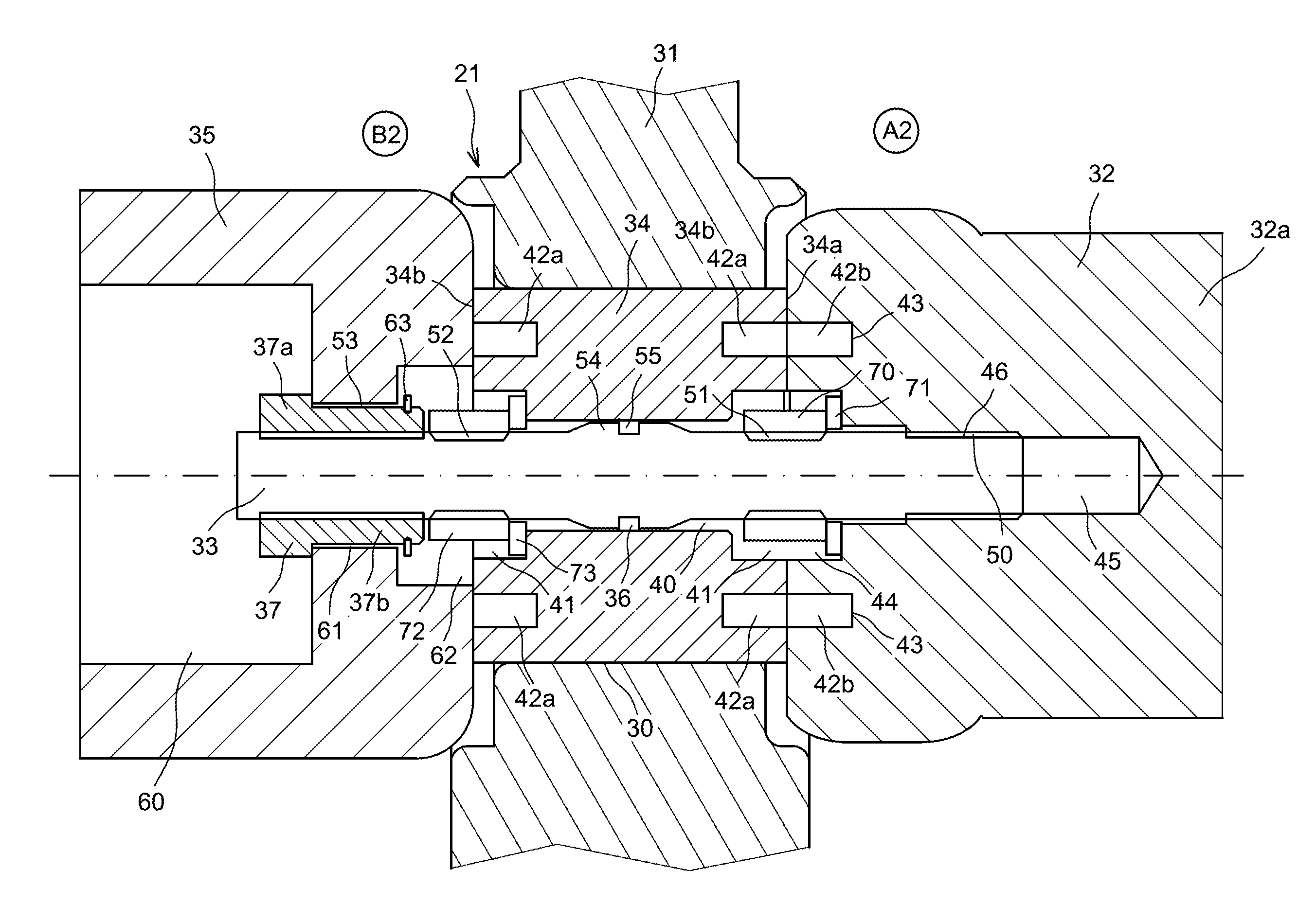
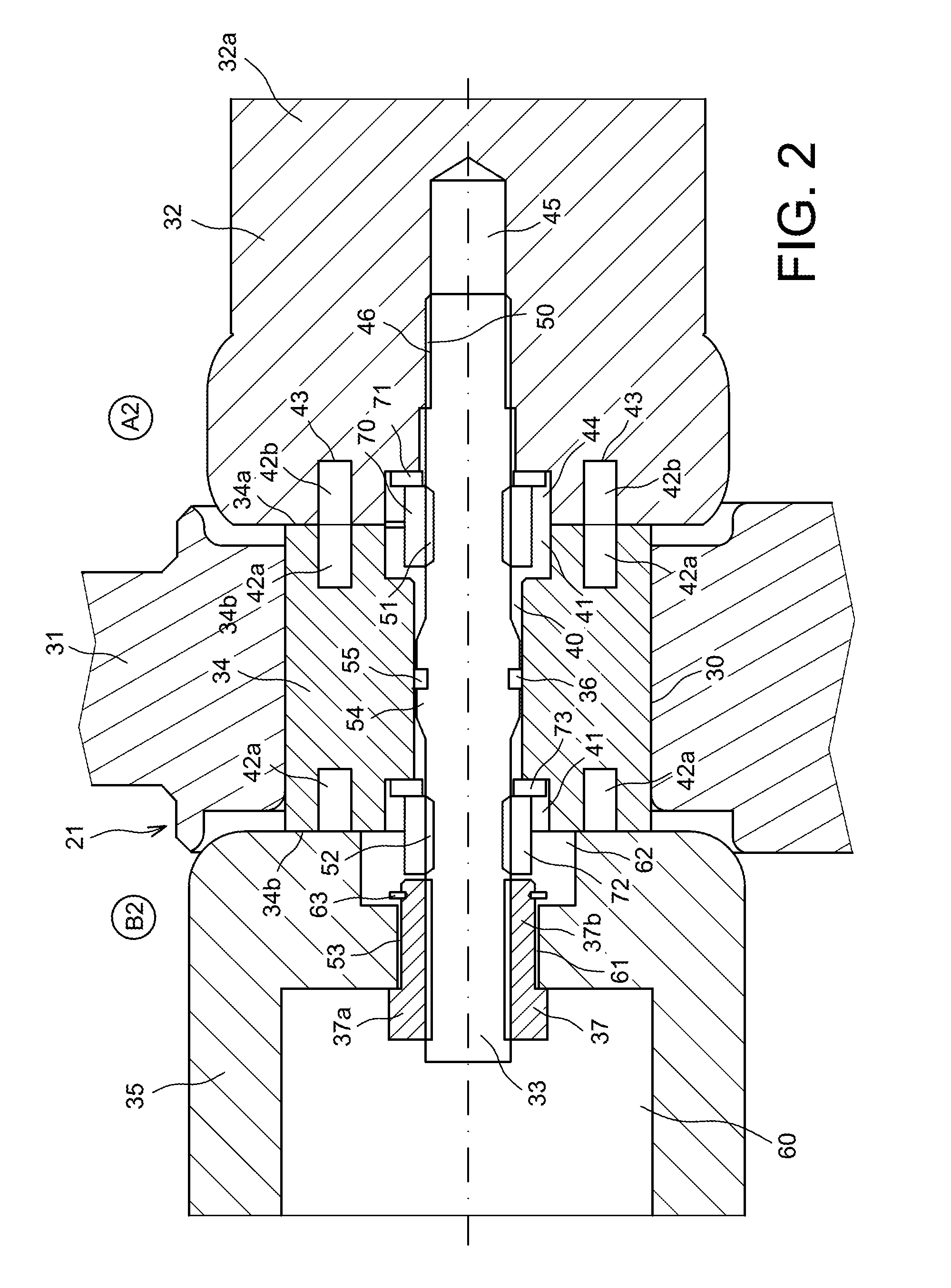
[0046]FIG. 2 shows a supporting insulator 31 separating two compartments A2 and B2 filled with gas under pressure. A conductor 32, in this example a portion of a busbar, and a bush 35 are mounted on the supporting insulator 31 by means of a fastener device 21. The fastener device 21 comprises a threaded shank 33 and a ring 34.

[0047]The two compartments A2 and B2 are formed in a GIS tank (not shown).

[0048]The supporting insulator 31 is electrically insulating and is made of polyester resin or epoxy resin type materials. The ring 34 is placed in the supporting insulator 31. In this embodiment, the insulator 31 is made by overmolding around the ring 34. Alternatively, and by way of example, the ring 34 is inserted into the insulator 31 at the time of final mounting.

[0049]The ring 34 is an annular element extending between two plane faces 34a and 34b. On each of its two faces, the ring 34 presents a bore 41 and holes 42a placed around the bore 41. In this embodiment, two holes 42a are f...


PUM


Abstract

A fastener device for a gas-insulated substation (GIS) type installation comprising a threaded shank and a ring including a duct configured to receive the threaded shank, the ring being housed in a supporting insulator of the invention.

Description

TECHNICAL FIELD[0001]The invention relates to the assembly of high- or medium-voltage gas-insulated substations (GIS). Substations of this type comprise switchgear, in particular busbar section isolators, circuit breakers, or grounding switches. Such pieces of switchgear are generally insulated from one another using sulfur hexafluoride (SF6) in tanks under pressure.[0002]The invention relates more particularly to a fastener device for use in such compartmentalized installations at medium or high voltage.[0003]A distinction can be made between different types of GIS: single-phase installations and three-phase installations. In single-phase installations, a tank contains only the live portions of a single phase. In three-phase equipment, a tank contains the live portions of three phases.[0004]The present invention applies both to single-phase GISs and to three-phase GISs.[0005]The invention may also be used for any type of compartmentalized equipment at medium or high voltage, e.g. i...

Claims


Application Information

Patent Timeline
Patent Type & Authority Patents(United States)
IPC IPC(8): H01R13/02H01R13/52H02G5/06H01R43/20
CPCH01R13/5219H01R43/20H02G5/068
Inventor GERBER, PHILIPLUSCHER, ROBERTTREIER, LUKAS
Owner ALSTOM TECH LTD
Learn More