
Image forming apparatus and lifetime judgment system

a technology of image forming apparatus and life judgment system, which is applied in the direction of electrographic process apparatus, instruments, optics, etc., can solve the problems of inconvenient use for users who cannot use the device for a long time, difficult to uniformly judge the lifetime of parts in accordance with the conventional standard, and inability to accurately estimate the lifetime of parts. , to achieve the effect of ensuring the image quality above a certain degr

Active Publication Date: 2018-12-20
KONICA MINOLTA INC
View PDF2 Cites 1 Cited by
  • Summary
  • Abstract
  • Description
  • Claims
  • Application Information

AI Technical Summary

Benefits of technology

The technical effect of this patent is to provide an image forming apparatus and lifetime judgment system that can detect changes in the surface condition of the fixing member using only the usual mechanism. Additionally, it aims to secure image quality even if the surface condition of the fixing member changes using only the usual mechanism.

Problems solved by technology

In a device installed in an office or the like, such as a multi function peripheral having a copy function, a scan function, a print function and the like, in case that the part of the device is replaced after the lifetime of the part is ended and the part is ordered, it is inconvenient for a user to be unable to use the device for a long time.
However, it is difficult to accurately estimate the lifetime of each part only by using the regular report.
Further, because the allowable range of the image quality is varied according to the users, it is difficult to uniformly judge the lifetime of the part in accordance with the conventional standard, such as the operation time, the number of paper sheets used in the printing, and the like.
From the above-described reasons, in accordance with the conventional standard, such as the operation time, the number of paper sheets used in the printing, and the like, it is difficult to judge whether the gloss memory is caused at the level in which there is some possibility that a complaint is made by the user (at the level in which the lifetime of the member is ended).
However, because the optical sensor has the low durability to a high temperature, it is practically difficult to detect the roughness of the surface of the fixing member in the overall width thereof when the temperature of the fixing member is high.
Further, in the conventional method and the method disclosed in Japanese Patent Application Publication No. 2016-206635, because it is not possible to detect the degradation condition of the fixing member at a high accuracy, it is difficult to execute the process in which it is necessary to grasp the accurate degradation condition, for example, the process for changing the fixing control parameter used in the fixing step of the image forming in accordance with the degradation condition of the fixing member.

Method used


Image

  • Image forming apparatus and lifetime judgment system
  • Image forming apparatus and lifetime judgment system
  • Image forming apparatus and lifetime judgment system

Examples


first embodiment

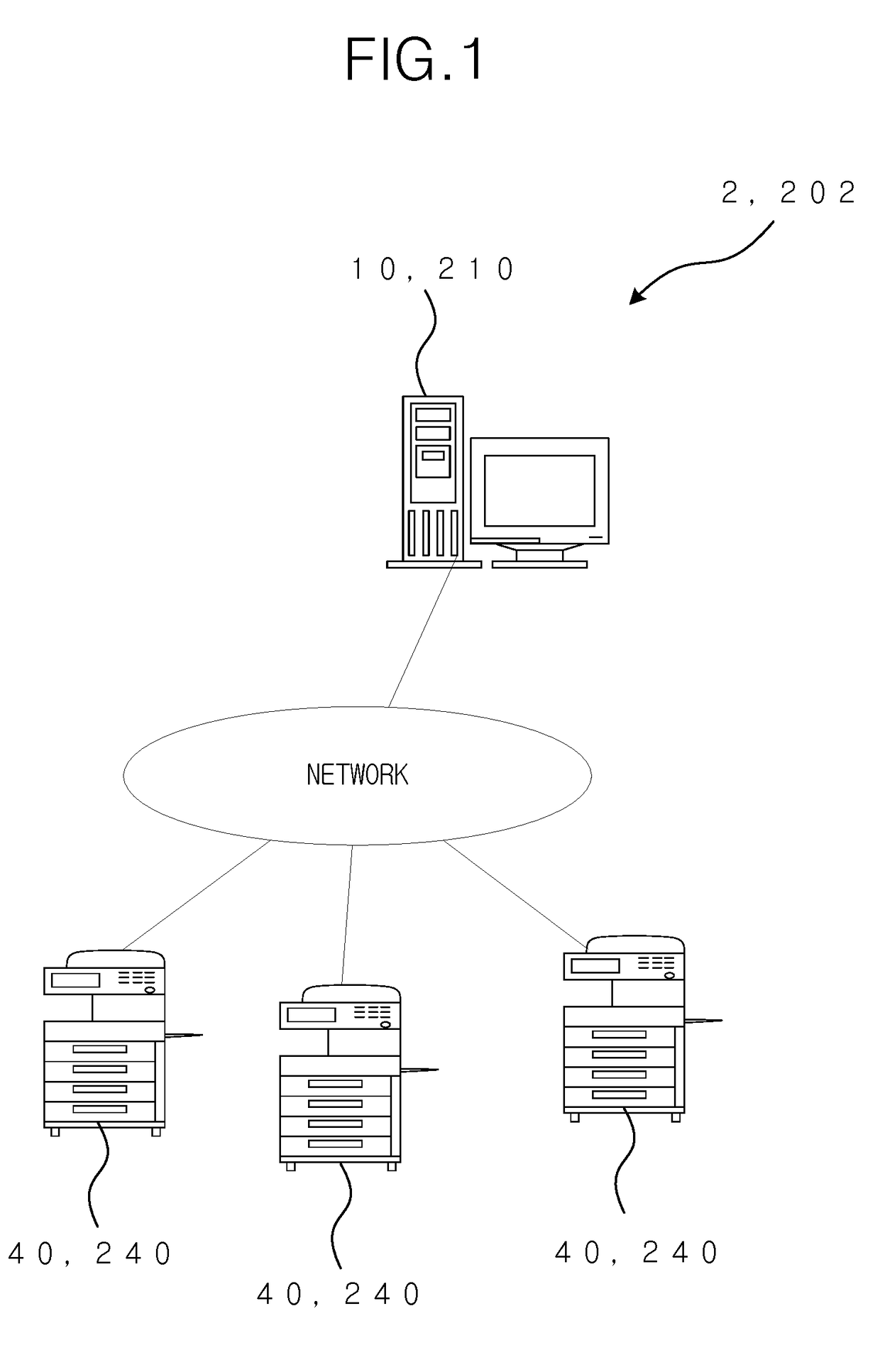
[0032]FIG. 1 shows a configuration example of the maintenance management system 2 according to the first embodiment. In the maintenance management system 2, the management server 10 which is the maintenance management device is connected with a plurality of image forming apparatuses 40 via a network, such as the Internet. The management server 10 is installed in a maintenance company for maintaining and managing the image forming apparatuses 40, or the like, and each image forming apparatus 40 is installed in an office or the like of each user.

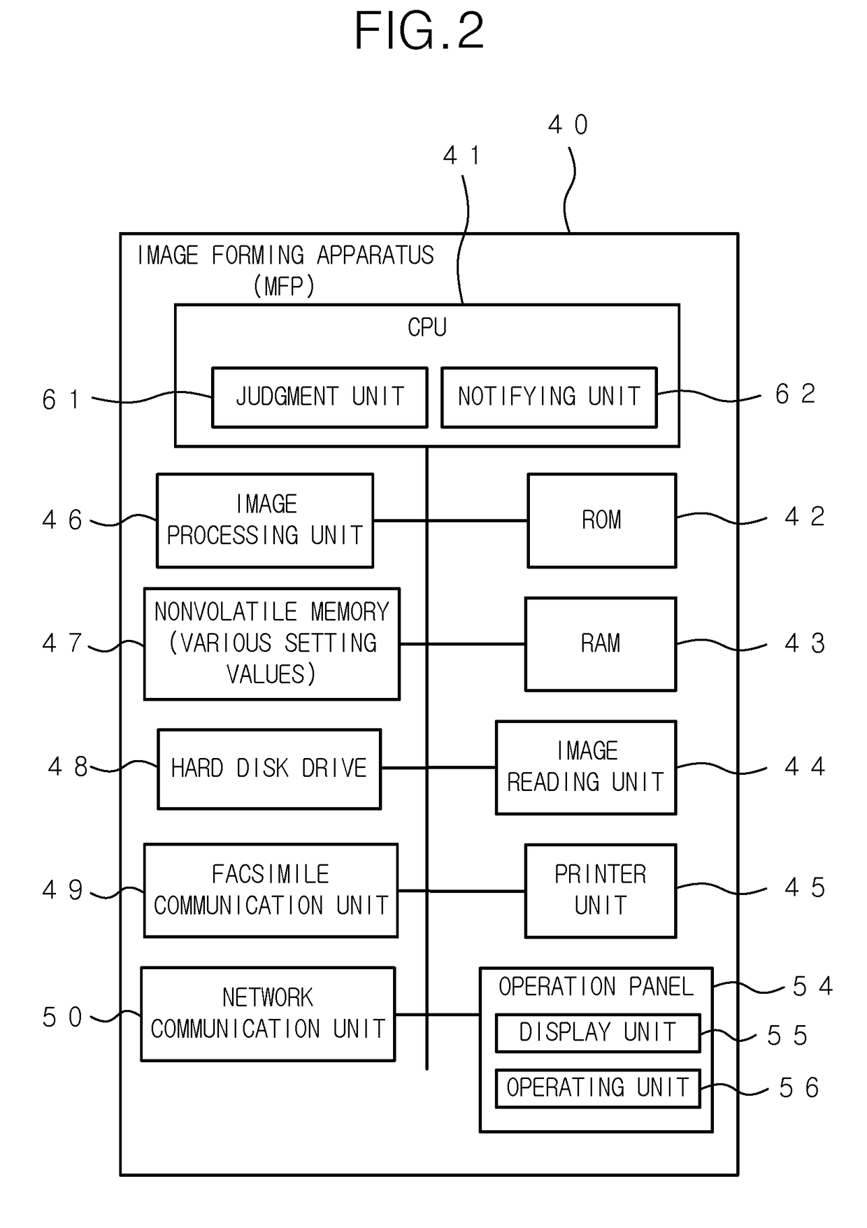
[0033]The image forming apparatus 40 is a so-called multi function peripheral which has a copy function for printing an image of an original on a recording sheet by optically reading the original, a scan function for storing the image data obtained by optically reading an original as a file and transmitting the image data to an external terminal via the network, a print function for printing an image in accordance with the print data received ...

second embodiment

[0081]Next, the maintenance management system 202 according to the second embodiment will be explained. As shown in FIG. 1, the maintenance management system 202 comprises a plurality of image forming apparatuses 240 and a management server 210 which is the maintenance management device, and has the same configuration as the maintenance management system 2 according to the first embodiment.

[0082]The image forming apparatus 240 is a so-called multi function peripheral like the image forming apparatus 40 according to the first embodiment. In the second embodiment, each image forming apparatus 240 judges the degradation progress of the fixing member for fixing the image on the paper sheet in the printing by the method which will be explained below, and changes the fixing control parameter for the image forming in accordance with the above judgment result to maintain the image quality above a certain level. Further, when the life of the fixing member is exhausted, the image forming appa...


PUM


Abstract

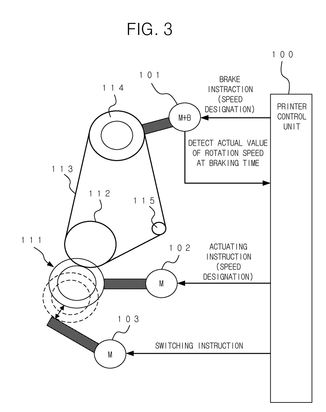
Disclosed is image forming apparatus, including a first roller and a second roller that conveys the recording sheet by sandwiching the recording sheet in a fixing process of an image forming; a pressing actuator that presses the first roller and the second roller against each other; an actuating motor that actuates the first roller; a brake that applies a brake force to the second roller; a rotation speed detector that detects a rotation speed of the second roller; and a hardware processor that judges a degradation of each surface roughness of the first roller and the second roller in accordance with the rotation speed of the second roller, which is detected when the first roller is actuated in a situation in which the first roller and the second roller are pressed against each other and when the brake applies a predetermined brake force to the second roller.

Description

[0001]The entire disclosure of Japanese Patent Applications No. 2017-118878 filed on Jun. 16, 2017 and No. 2017-158665 filed on Aug. 21, 2017, is incorporated herein by reference in its entirety.BACKGROUNDTechnological Field[0002]The present invention relates to an image forming apparatus and a life judgment system which manage the replacement timing of the replacement part. Further, the present invention relates to an image forming apparatus which changes the fixing control parameter relating to the fixing of the image.Description of the Related Art[0003]In a device installed in an office or the like, such as a multi function peripheral having a copy function, a scan function, a print function and the like, in case that the part of the device is replaced after the lifetime of the part is ended and the part is ordered, it is inconvenient for a user to be unable to use the device for a long time. Therefore, the regular report indicating the usage amount and the like of each replaceme...

Claims


Application Information

Patent Timeline
IPC IPC(8): G03G15/00G03G15/20
CPCG03G15/55G03G15/2039G03G15/2028G03G15/2032G03G15/2064G03G2215/2032G03G2215/2045
Inventor OGATA, SATOSHI
Owner KONICA MINOLTA INC
Learn More