Vehicle

Inactive Publication Date: 2018-12-20
HONDA MOTOR CO LTD
View PDF7 Cites 1 Cited by
  • Summary
  • Abstract
  • Description
  • Claims
  • Application Information

AI Technical Summary

Benefits of technology

The technical effect of this patent is to prevent unnecessary decrease in the storage amount of the energy storage device in a vehicle by releasing the regeneration preparation state based on the relative position and speed of other vehicles. This allows for better utilization of the energy storage device and improved efficiency of the vehicle's energy management system.

Problems solved by technology

In the technique of JP-A-2003-025869 described above, since the automatic engine brake control is performed by the gear change of the transmission, the technique described above cannot be applied to a vehicle such as an electric vehicle having no transmission.
In other words, when the energy storage device is in a state close to a full charge state, the regenerative electric power cannot be charged in the energy storage device, so that a regenerative operation of the electric motor cannot be performed.
When the relative speed with respect to the other vehicle is large, a large deceleration is necessary, and thus the amount of the regenerative electric power generated by the rotating electric machine at deceleration regeneration is likely to be large.
On the contrary, when the relative speed is small, a large deceleration is not necessary, and thus the amount of the regenerative electric power generated by the rotating electric machine at deceleration regeneration is likely to be small.
For this reason, despite the small relative speed, when the regeneration preparation state is set, the storage amount of the energy storage device is unnecessarily reduced.
When the distance to the other vehicle is short, a large deceleration is necessary, and thus the amount of the regenerative electric power generated by the rotating electric machine at deceleration regeneration is likely to be large.
On the contrary, when the distance is long, a large deceleration is not necessary, and thus the amount of the regenerative electric power generated by the rotating electric machine at deceleration regeneration is likely to be small.
For this reason, despite the long distance, when the regeneration preparation state is set, the storage amount of the energy storage device is unnecessarily reduced.

Method used


Image

  • Vehicle
  • Vehicle
  • Vehicle

Examples


Embodiment Construction

[0035]Hereinafter, embodiments of a vehicle according to the invention will be described with reference to the drawings.

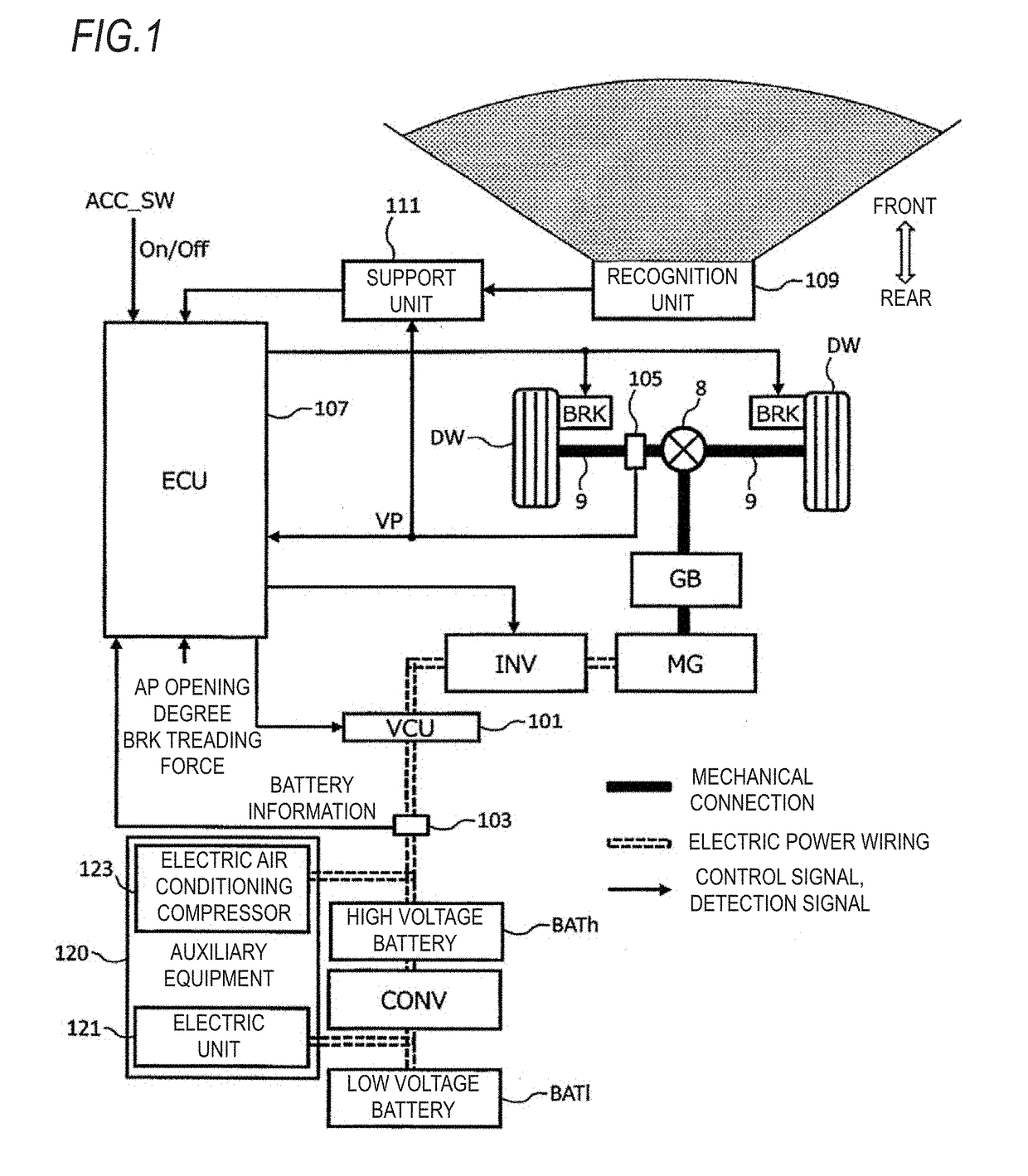
[0036]FIG. 1 is a block diagram which illustrates an internal configuration of the vehicle according to the embodiment. In FIG. 1, the thick solid line indicates the mechanical connection, the double dotted line indicates the electric power wiring, and the thin solid line arrow indicates the control signal or the detection signal.

[0037]The vehicle illustrated in FIG. 1 includes a motor generator (MG), a gear box (hereinafter simply referred to as a “gear”) GB, a high voltage battery BATh (an energy storage device), a converter CONV, a low voltage battery BATl, a Voltage Control Unit (VCU) 101, an inverter INV, a battery sensor 103, a vehicle speed sensor 105, a brake BRK, an ECU 107, a recognition unit 109, and a support unit 111. The vehicle is a so-called electric vehicle travelling with the power output by the motor generator MG.

[0038]Hereinafter, each component...


PUM


Abstract

A vehicle which includes an energy storage device, a rotating electric machine, a recognition unit for recognizing an other vehicle in front, a support unit, and a control unit configured to controlling charge and discharge of the rotating electric machine and the energy storage device according to support control of the support unit. When travelling is performed in accordance with support control, and the support unit predicts or detects that the other vehicle is in a near space closer to the vehicle than a space which satisfies the predetermined positional relationship ahead in a travelling direction of the vehicle based on recognized contents of the recognition unit, the control unit sets a regeneration preparation state where an allowable charging electricity amount, by which the energy storage device can be charged by regenerative electric power generated by the rotating electric machine operating as a generator, is increased.

Description

CROSS-REFERENCE TO RELATED APPLICATION[0001]The present application claims the benefit of priority of Japanese Patent Application No. 2017-117057, filed on Jun. 14, 2017, the content of which is incorporated herein by reference.BACKGROUND1. Field of the Invention[0002]The present invention relates to a vehicle.2. Description of the Related Art[0003]In recent years, various driving support devices have been developed and put to practical use to reduce the burden on drivers of vehicles and to avoid accidents. As one of such driving support devices, a device having an adaptive cruise control function (hereinafter referred to as an “ACC function”) is known.[0004]In general, the ACC function is premised on being used when travelling is performed on an expressway where the operation frequency of an accelerator and a brake is relatively low. The driving support device sets a target speed when the driver performs an operation to activate the ACC function and carries out constant speed trave...

Claims


Application Information

Patent Timeline
IPC IPC(8): B60W30/16B60W30/18B60W20/30F16H61/08F16H59/60
CPCB60K31/042B60W10/08B60W2550/302B60W2550/306B60W30/162B60W30/18136B60W30/18127B60W20/30F16H61/08F16H59/60B60K6/485B60L7/10B60W10/18B60W10/26B60W30/16B60W2710/248B60W2710/08B60W2520/10B60W2554/80B60W2554/801B60K31/0008B60K31/00B60W2710/244B60L2240/12B60L1/003B60L7/08B60L58/12B60W2554/804B60W2754/30B60W2554/00Y02T10/72Y02T10/70Y02T10/7072Y02T90/14B60W2554/4041
Inventor ISHIKAWA, HISASHI
Owner HONDA MOTOR CO LTD
Why Eureka
Try Eureka