
Method for modeling additive manufacturing of a part

Inactive Publication Date: 2018-12-13
RAYTHEON TECH CORP
View PDF2 Cites 11 Cited by
  • Summary
  • Abstract
  • Description
  • Claims
  • Application Information

AI Technical Summary

Benefits of technology

The patent is about a method for modeling and controlling additive manufacturing of a part using a process map that takes into account various factors such as energy equation, phase field equation, concentration equation, and stress equation. The method involves creating a model for estimating the output of the manufacturing process based on the part design, energy equation, and additional relationships, and then entering the operating parameters into the model to produce an output. The output is then compared to acceptable criteria, and additional operating parameters are added to the process map if the output is found to be acceptable. The method can be used for complex near-net-shaped parts produced from alloys, which can be validated and calibrated based on the characteristics of the physical part. The technical effects of this method are improved accuracy in predicting the quality of the manufactured part and improved control over the process parameters for producing high-quality parts.

Problems solved by technology

Despite the advance of such technology, the challenge remains to repeatedly produce high quality components with minimal distortion, minimal residual stress and little or no amount of cracking and other defects.
These issues are currently addressed by conducting expensive time and resource intensive experimentation whereby a component is produced and then analyzed using a trial and error approach, with results of the analysis leading to adjustments for the next attempt.
However, crack propensity in articles manufactured through additive manufacturing is highly non-linear, and the energy-based analysis is therefore in need of further improvement.

Method used


Image

  • Method for modeling additive manufacturing of a part
  • Method for modeling additive manufacturing of a part
  • Method for modeling additive manufacturing of a part

Examples


Embodiment Construction

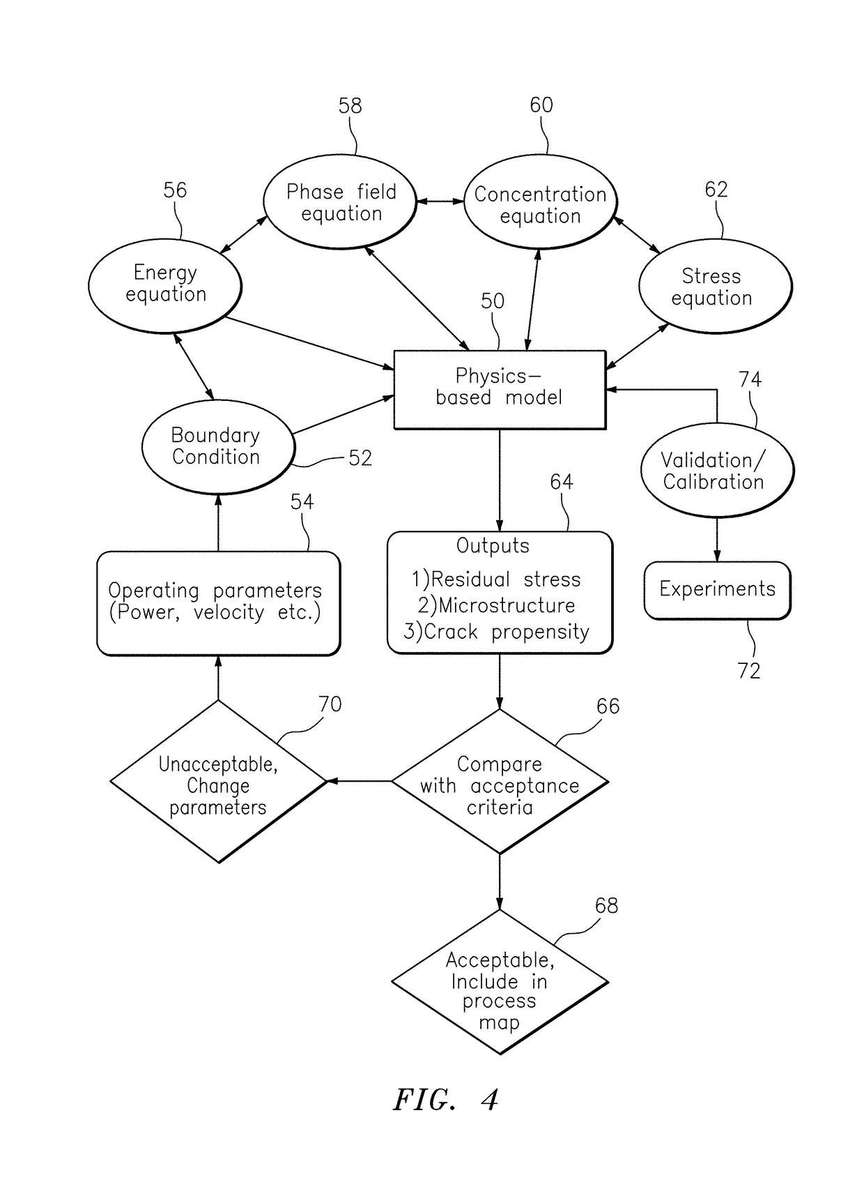
[0026]The present disclosure relates to the field of additive manufacturing and, more particularly, to a method for modeling an additive manufacturing process in order to develop a process map or series of process models at different process parameters which can be used to produce actual physical products or workpieces with reduced crack propensity, reduced residual stress and a desirable microstructure.

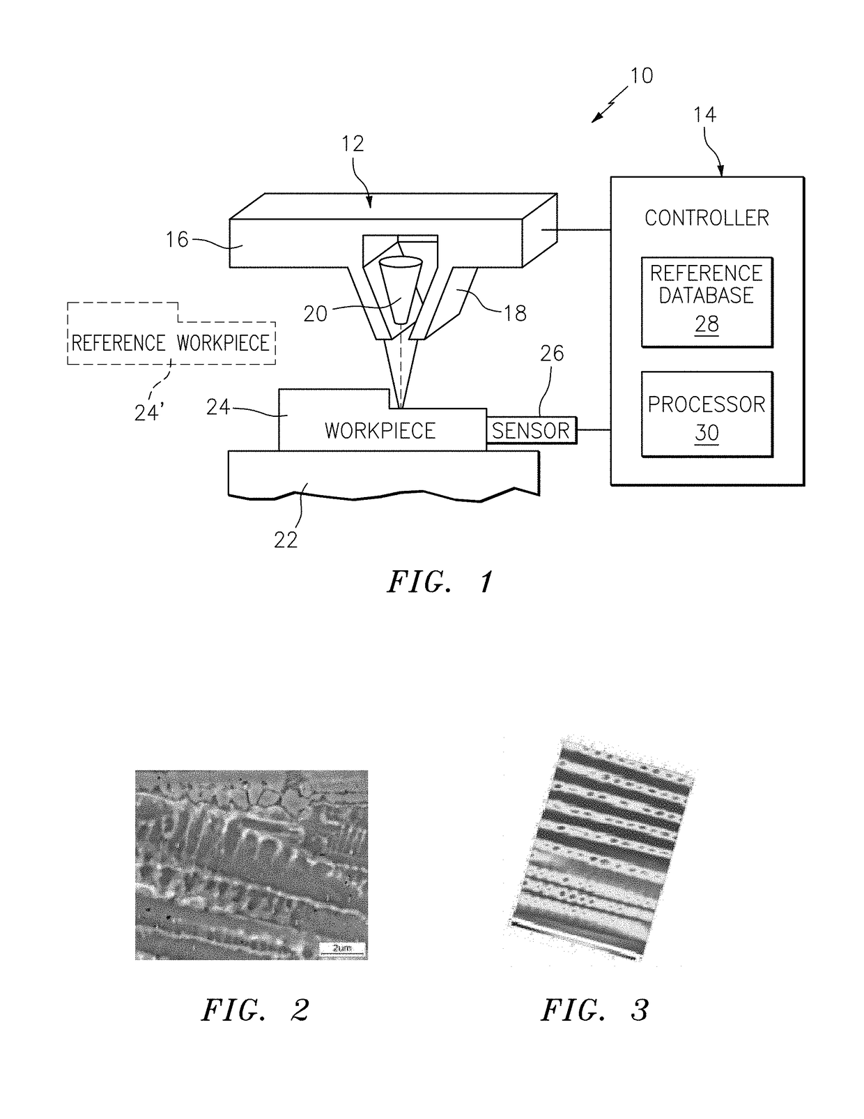
[0027]FIG. 1 illustrates a typical additive manufacturing system 10, which has an additive manufacturing tool 12 and a controller 14. Additive manufacturing tool 12 has a material reservoir 16, material dispensers 18, a laser guide 20, a platform 22 for a workpiece 24, and a sensor 26 which communicates with controller 14.

[0028]Controller 14 typically includes a reference database 28 and processor 30. Reference database 28 contains relevant data and processor 30 contains programming to control additive manufacturing tool 12 to produce parts as is known to a person of ordinary skill i...


PUM

PropertyMeasurementUnit
Speedaaaaaaaaaa
Microstructureaaaaaaaaaa
Velocityaaaaaaaaaa

Abstract

A method for modeling additive manufacturing of a part, includes (i) constructing a model for estimating output of a simulated additive manufacturing process based upon part design, energy equation and at least one additional relationship selected from the group consisting of phase field equation, concentration equation and stress equation; (ii) entering process operating parameters into the model to produce an output; (iii) comparing the output to acceptance criteria to determine whether the output is acceptable or unacceptable; (iv) for acceptable output, adding operating parameters which resulted in the acceptable output to a process map for additive manufacturing the part; and (v) repeating steps (ii) through (iv) for different operating parameters until the process map is complete.

Description

BACKGROUND[0001]The present disclosure relates generally to additive manufacturing and, more particularly to a method for modeling additive manufacturing of a part to reduce crack propensity and residual stress.[0002]Powder bed and directed energy additive manufacturing techniques are becoming more widely adopted for production of complex near-net-shaped parts. Additive manufacturing offers increased design freedom and enables designers and engineers to create unique products.[0003]Despite the advance of such technology, the challenge remains to repeatedly produce high quality components with minimal distortion, minimal residual stress and little or no amount of cracking and other defects. These issues are currently addressed by conducting expensive time and resource intensive experimentation whereby a component is produced and then analyzed using a trial and error approach, with results of the analysis leading to adjustments for the next attempt.[0004]Energy-based approaches have b...

Claims


Application Information

Patent Timeline
IPC IPC(8): G05B17/02B33Y50/02
CPCG05B17/02B22F3/1055B22F2003/1057B33Y50/02G05B13/041G05B13/042G05B19/4099G05B2219/49013G05B2219/49023G05B2219/49029G05B2219/49027Y02P90/02Y02P10/25B22F10/31B22F10/36B22F10/366B22F10/25B22F10/28B22F10/38B22F10/85
Inventor ACHARYA, RANADIPSTAROSELSKY, ALEXANDERSHARON, JOHN A.EL-WARDANY, TAHANY IBRAHIM
Owner RAYTHEON TECH CORP
Learn More