Shock absorber with comfort valve
a technology of shock absorber and comfort valve, which is applied in the direction of shock absorbers, mechanical equipment, transportation and packaging, etc., can solve the problems of not being very comfortable, affecting the comfort of users, and the movement behavior of vehicles being damaged,
- Summary
- Abstract
- Description
- Claims
- Application Information
AI Technical Summary
Benefits of technology
Problems solved by technology
Method used
Image
Examples
first embodiment
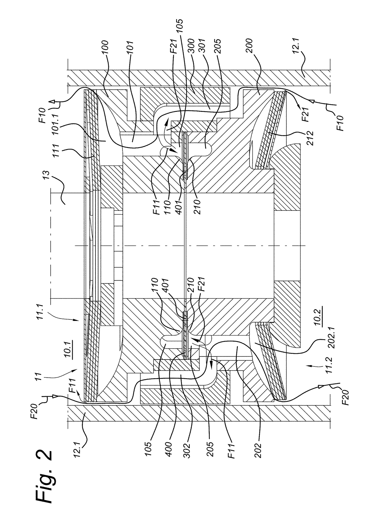
[0070]The piston is shown in more detail and in cross-section in FIG. 2. A top or first side 11.1 of the piston is directed towards and associated with the first cylinder chamber 10.1, and a bottom or second side 11.2 of the piston is directed towards and associated with the second cylinder chamber 10.2.
[0071]A first main channel 301, 101 passes through the piston 11 to allow for a first main fluid flow F10 from the second side 11.2 to the first side 11.1 of the piston and therefore from the second cylinder chamber 10.2 to the first cylinder chamber 10.1. A first main non-return valve 111 is arranged at the piston first side 11.1 and is associated with the first main channel 301, 101 so as to open for fluid flow from the second cylinder chamber 10.2 through the first main channel towards the first cylinder chamber 10.1 and piston first side 11.1. The first main non-return valve 111 is closed for fluid flow in the opposite direction, although may allow for a small constant fluid flo...
second embodiment
[0081]An auxiliary valve 400 in the form of an annular plate valve is provided in between the first and second central members 100, 200 in the second embodiment and its variant, such that fluid may flow past auxiliary valve 400 in a neutral or rest position thereof. The neutral position of the auxiliary valve is shown in FIGS. 2 and 6. The annular plate valve 400 is clamped at its internal perimeter between first and second central members 100, 200. The external perimeter of auxiliary annular plate valve 400 is left free to move between the first and second central members. The auxiliary annular plate valve 400 is further provided with openings 401 to allow passage of fluid from first annular central member groove 105 to second annular central member groove 205, or vice versa. FIGS. 9a and 9b show top views on two embodiments of an annular plate valve 400. The embodiment of FIG. 9a has multiple round openings 401, while the embodiment of FIG. 9b has elongated openings. Various other...
PUM
 Abstract
Description
Claims
Application Information
 - R&D
- Intellectual Property
- Life Sciences
- Materials
- Tech Scout
- Unparalleled Data Quality
- Higher Quality Content
- 60% Fewer Hallucinations
Browse by: Latest US Patents, China's latest patents, Technical Efficacy Thesaurus, Application Domain, Technology Topic, Popular Technical Reports.
© 2025 PatSnap. All rights reserved.Legal|Privacy policy|Modern Slavery Act Transparency Statement|Sitemap|About US| Contact US: help@patsnap.com


