
Sidelap interconnect for photovoltaic roofing modules

a photovoltaic roof and sidelap technology, applied in the direction of photovoltaic supports, heat collector mountings/supports, lighting and heating apparatus, etc., can solve the problems of damage to exterior and/or interior roofing structures, non-uniform appearance of roof structures, and disruption of the more uniform aesthetic achieved by traditional roofs

Active Publication Date: 2018-12-06
TESLA INC
View PDF3 Cites 14 Cited by
  • Summary
  • Abstract
  • Description
  • Claims
  • Application Information

AI Technical Summary

Benefits of technology

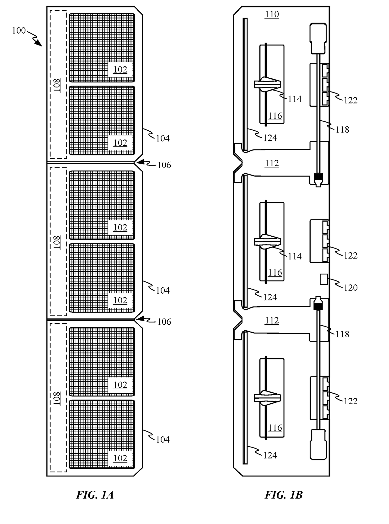
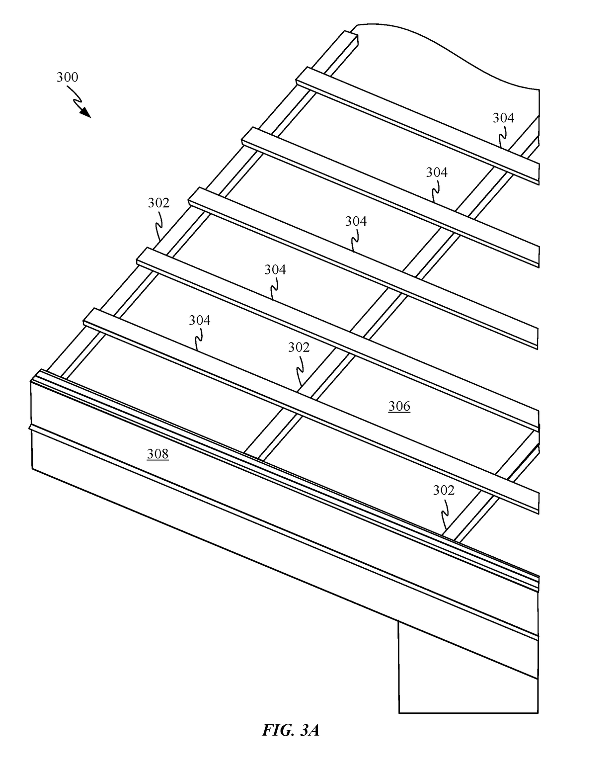
This patent describes various methods and apparatus for incorporating photovoltaic modules into a roofing structure. The invention includes a roofing module with a sidelap that separates two drainage channels, and a water drainage component comprising an alignment ridge. The sidelap also includes flow directors to evenly distribute water across the photovoltaic modules. The base component is separate and distinct from the water drainage component and is attached to the water drainage component by sliding it into a drainage channel. Additionally, the roofing structure includes a lattice of battens and counter-battens, with the attachment feature securing the first batten to a first roofing module and the standoff in contact with a second batten. The technical effects of the invention include efficient water drainage and improved distribution of sunlight across the photovoltaic modules, resulting in enhanced performance and reliability of the roofing structure.

Problems solved by technology

Unfortunately, this can leave the roofing structure with a non-uniform appearance that many home or business owners would rather avoid.
These conventional installations can include large panels that disrupt the more uniform aesthetic achieved by a traditional rooftop.
In some cases, solar panel installation can even cause damage to exterior and / or interior roofing structures.

Method used


Image

  • Sidelap interconnect for photovoltaic roofing modules
  • Sidelap interconnect for photovoltaic roofing modules
  • Sidelap interconnect for photovoltaic roofing modules

Examples


Embodiment Construction

[0039]This description is presented to enable any person skilled in the art to make and use the embodiments, and is provided in the context of a particular application and its requirements. Various modifications to the disclosed embodiments will be readily apparent to those skilled in the art, and the general principles defined herein may be applied to other embodiments and applications without departing from the spirit and scope of the present disclosure. Thus, the invention is not limited to the embodiments shown, but is to be accorded the widest scope consistent with the principles and features disclosed herein.

[0040]One way to avoid aesthetic problems generally associated with roof-mounted photovoltaic modules is to incorporate the photovoltaic modules into the roof itself. The photovoltaic modules can be incorporated into the roof by using photovoltaic modules taking the form of solar roofing modules to construct an exterior layer of the roof. Unfortunately, incorporating the p...


PUM


Abstract

This disclosure describes methods and apparatus for assembly a roofing structure that incorporates photovoltaic modules as shingles of the roofing structure. A sidelap is used to both establish consistent spacing between the solar shingles and prevent water passing between adjacent shingles from collecting beneath the solar shingles by guiding the water passing through the solar shingles and redirecting the water down-roof. In some embodiments, the sidelaps can have additional functionality. For example, a sidelap can include tabs configured to interact with lateral securing features positioned on downward-facing surfaces of the solar roofing modules to help keep the lateral sides of the photovoltaic modules from pulling away from the roofing structure during severe weather conditions. The sidelap could also include means for attaching a wire clip to one end of the sidelap.

Description

CROSS-REFERENCES TO RELATED APPLICATIONS[0001]This application claims priority under 35 USC 119(e) to U.S. Provisional Application No. 62 / 515,434, entitled “MULTI-REGION SOLAR ROOFING MODULES” and filed on Jun. 5, 2017, the contents of which are incorporated in their entirety and for all purposes. This application is also related to U.S. patent application Ser. No. 15 / ______, (Applicant Reference No.: P371-2NUS), entitled “MULTI-REGION SOLAR ROOFING MODULES”, scheduled to be filed concurrently with the present application, the entirety of which is herein incorporated by reference.BACKGROUND[0002]Solar panels are generally added to select regions of an existing roofing structure. Unfortunately, this can leave the roofing structure with a non-uniform appearance that many home or business owners would rather avoid. These conventional installations can include large panels that disrupt the more uniform aesthetic achieved by a traditional rooftop. In some cases, solar panel installation ...

Claims


Application Information

Patent Timeline
IPC IPC(8): H02S20/25E04D1/12E04D1/30H01L31/048E04B1/62
CPCH02S20/25E04D1/12E04B1/62H01L31/048E04D1/30E04D1/365H01L31/02021H01L31/0508H02S40/32H02S20/23H02S40/34H02S40/36F24S25/613F24S2025/6002F24S2020/13Y02A30/60E04D1/2984Y02B10/10Y02E10/50H02S30/10
Inventor SEERY, MARTINMOLINA, DAVIDGUTHRIE, TREVOR B.ANDERSON, THOMASHEWLETT, JONATHAN
Owner TESLA INC
Learn More