
High speed, high density electrical connector

Active Publication Date: 2006-03-30
AMPHENOL CORP
View PDF11 Cites 162 Cited by
  • Summary
  • Abstract
  • Description
  • Claims
  • Application Information

AI Technical Summary

Benefits of technology

[0015] In another aspect, the invention relates to an electrical connector that has a plurality of regions. Each region has insulative material; a plurality of signal conductors, each signal conductor having a contact tail and a contact portion and an intermediate portion there between, and at least a part of the intermediat

Problems solved by technology

Electronic systems have generally become smaller, faster and functionally more complex.
As signal frequencies increase, there is a greater possibility of electrical noise being generated in the connector in forms such as reflections, cross-talk and electromagnetic radiation.

Method used


Image

  • High speed, high density electrical connector
  • High speed, high density electrical connector
  • High speed, high density electrical connector

Examples


Embodiment Construction

[0036] This invention is not limited in its application to the details of construction and the arrangement of components set forth in the following description or illustrated in the drawings. The invention is capable of other embodiments and of being practiced or of being carried out in various ways. Also, the phraseology and terminology used herein is for the purpose of description and should not be regarded as limiting. The use of “including,”“comprising,” or “having,”“containing,”“involving,” and variations thereof herein, is meant to encompass the items listed thereafter and equivalents thereof as well as additional items.

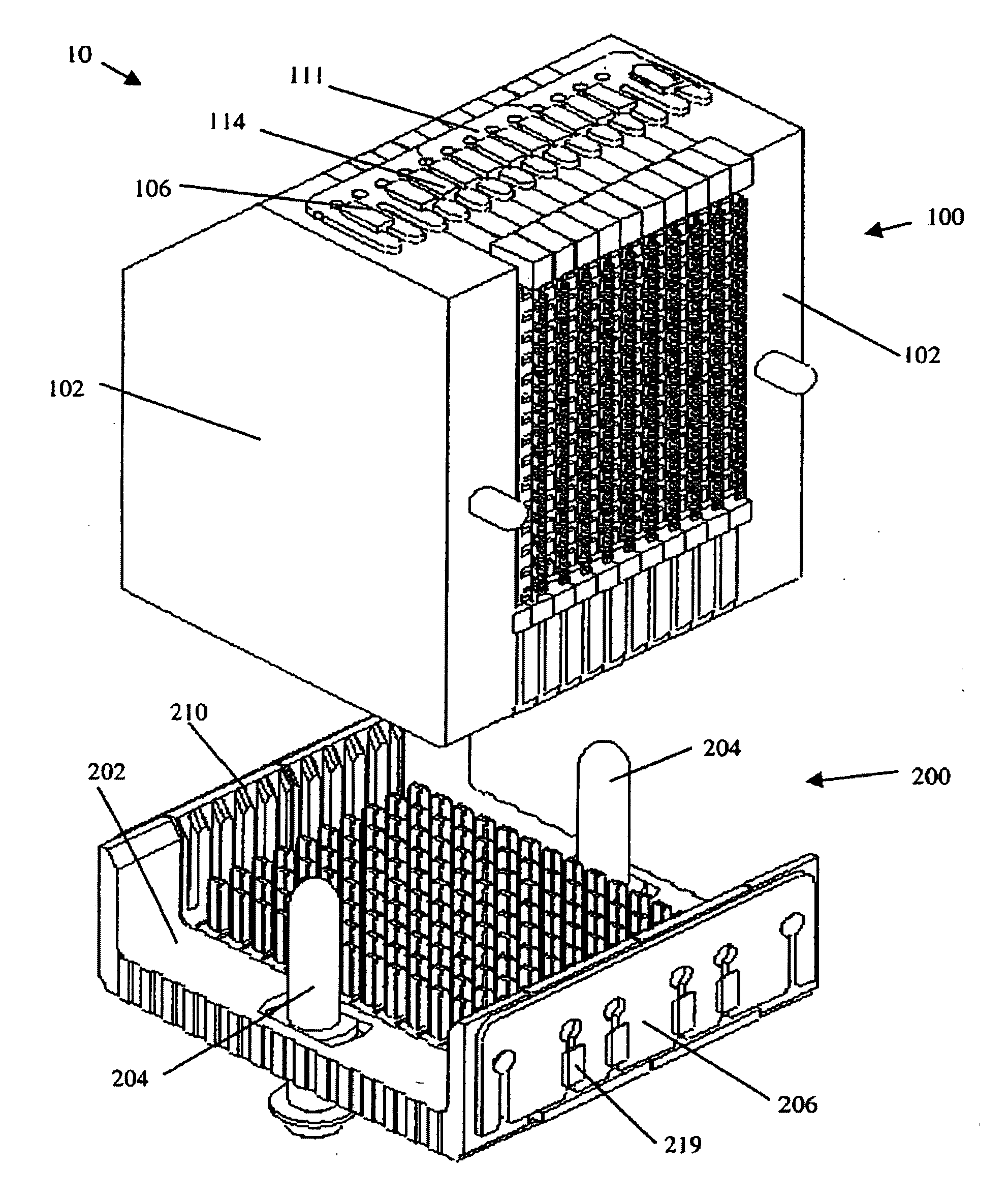
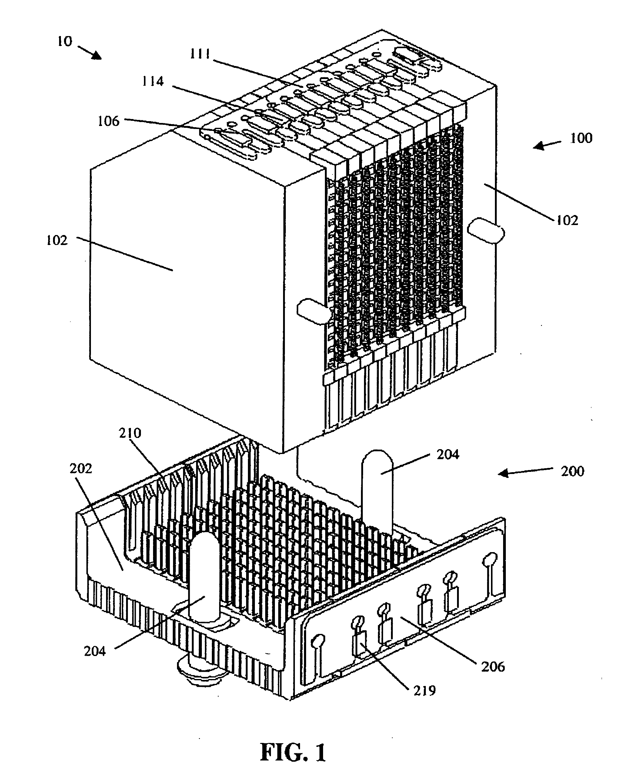
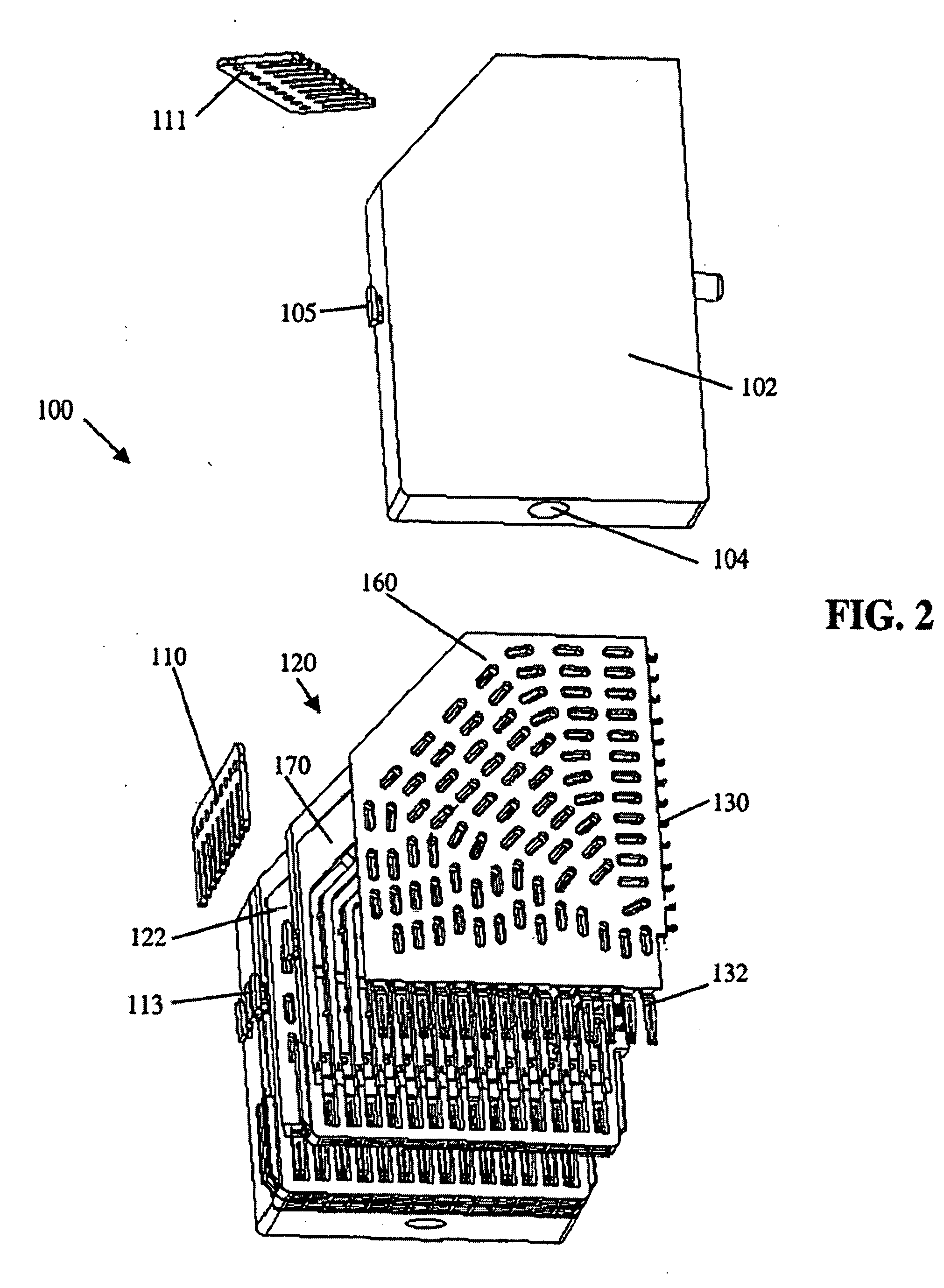
[0037] Referring to FIG. 1, there is shown an electrical connector assembly 10. The electrical connector assembly 10 includes a first electrical connector 100 mateable to a second electrical connector 200. Electrical connector 100 may be used as a daughter card connector and electrical connector 200 may be used as a backplane connector. However the invention m...


PUM

PropertyMeasurementUnit
Thicknessaaaaaaaaaa
Thicknessaaaaaaaaaa
Surface resistivityaaaaaaaaaa

Abstract

An electrical connector with electrically lossy materials bridging ground members. The lossy conductive members may be formed by filling a settable binder with conductive particles, allowing the partially conductive members to be formed through an insert molding process. Connectors assembled from wafers that contain signal conductors held within an insulative housing may incorporate lossy conductive members by having filled thermal plastic molded onto the insulatative housing. The lossy conductive members may be used in conjunction with magnetically lossy materials. The lossy conductive members reduce ground system do resonance within the connector, thereby increasing the high frequency performance of the connector.

Description

BACKGROUND OF INVENTION [0001] 1. Field of Invention [0002] This invention relates generally to an electrical interconnection systems and more specifically to improved signal integrity in interconnection systems. [0003] 2. Discussion of Related Art [0004] Electrical connectors are used in many electronic systems. It is generally easier and more cost effective to manufacture a system on several printed circuit boards (“PCBs”) which are then connected to one another by electrical connectors. A traditional arrangement for connecting several PCBs is to have one PCB serve as a backplane. Other PCBs, which are called daughter boards or daughter cards, are then connected through the backplane by electrical connectors. [0005] Electronic systems have generally become smaller, faster and functionally more complex. These changes mean that the number of circuits in a given area of an electronic system, along with the frequencies at which the circuits operate, have increased significantly in rec...

Claims


Application Information

Patent Timeline
IPC IPC(8): H01R13/648
CPCH01R13/514H01R13/719H01R23/688Y10T29/49204H01R13/46H01R43/16H05K1/0233H01R13/6587H01R13/6476H01R13/6585H01R13/6586H01R13/6599H01R12/00H01R12/721H01R13/6471
Inventor GAILUS, MARK W.
Owner AMPHENOL CORP
Learn More