
Systems and Methods for Detecting Damage in Wind Turbine Bearings

a technology of wind turbine bearings and systems, applied in the field of wind turbines, can solve the problems of insufficient clarity for low-speed bearing damage, insufficient time-consuming, and missed detection of failed components,

Active Publication Date: 2018-12-06
GENERAL ELECTRIC CO
View PDF3 Cites 8 Cited by
  • Summary
  • Abstract
  • Description
  • Claims
  • Application Information

AI Technical Summary

Benefits of technology

The present disclosure is directed to a method and system for detecting damage in a bearing of a wind turbine. The method involves collecting vibration data from sensors and analyzing it to identify harmonics that indicate bearing damage. The harmonics are eliminated and the remaining data is used to calculate a damage factor of the bearing. This factor is then compared to a predetermined threshold to determine if the bearing is damaged. The system includes a controller and memory store for storing and analyzing the vibration data. The technical effect of this patent is the ability to detect and locate damage in the bearing of a wind turbine quickly and accurately, which can help to prolong the life of the bearing and reduce downtime for maintenance.

Problems solved by technology

Though the primary fault frequencies for the inner race ball pass (IRBP) and the outer race ball pass (ORBP) in the enveloping spectrum have historically been used as a strong indicator for bearing damage of intermediate-speed and high-speed bearings, such frequencies often do not provide enough clarity for low-speed bearing damage.
Such inspection is inherently time consuming and can result in missed detection of failed components.
In addition, although manual inspection methods have been utilized with success, such methods do not provide a scalable option and result in reduced monitoring efficiency.
For at least the aforementioned reasons, the detection of low-speed bearing damage has proven difficult to automate using traditional detection analytics and / or trending techniques.
For low-speed planetary bearings in particular, there is currently no known method which can consistently and accurately detect and trend the energy of bearing damage propagation using traditional fast Fourier transform spectral analysis techniques.

Method used


Image

  • Systems and Methods for Detecting Damage in Wind Turbine Bearings
  • Systems and Methods for Detecting Damage in Wind Turbine Bearings
  • Systems and Methods for Detecting Damage in Wind Turbine Bearings

Examples


Embodiment Construction

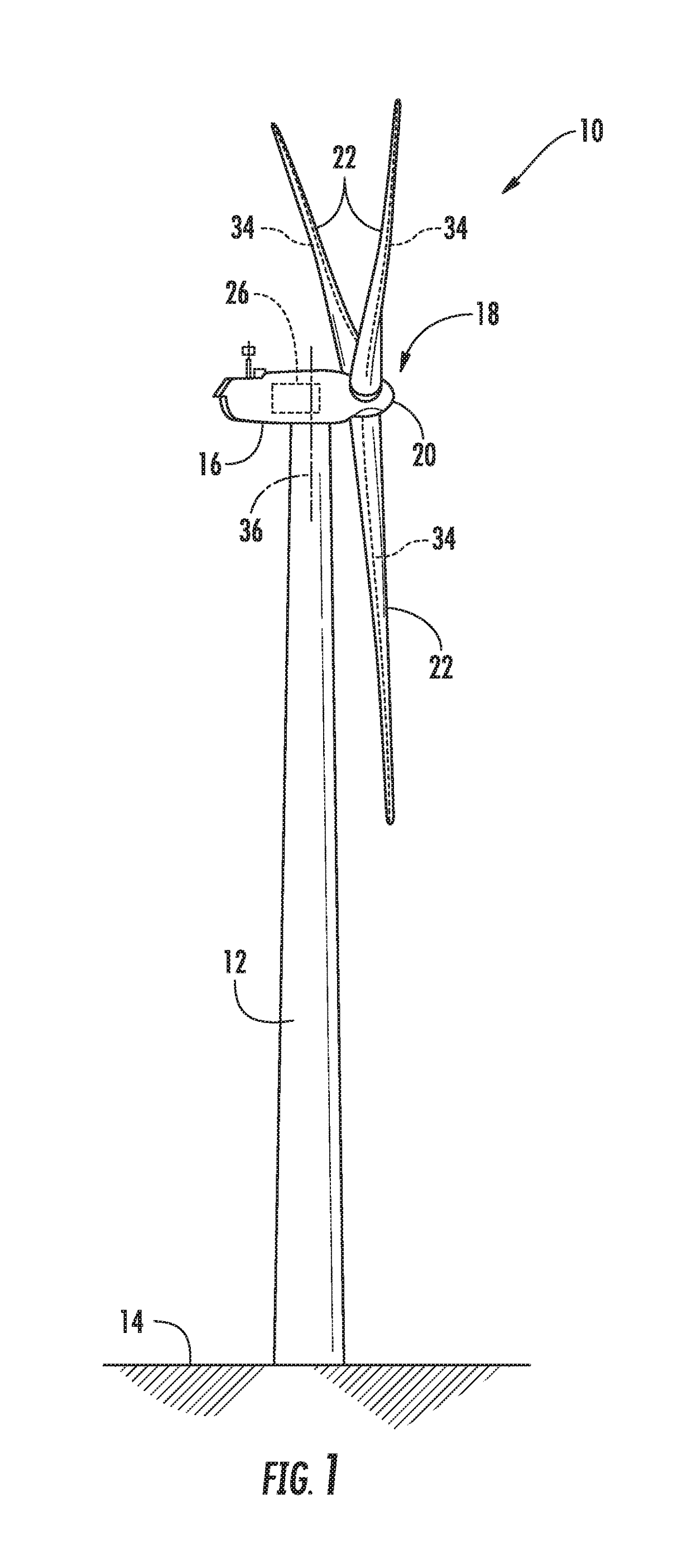
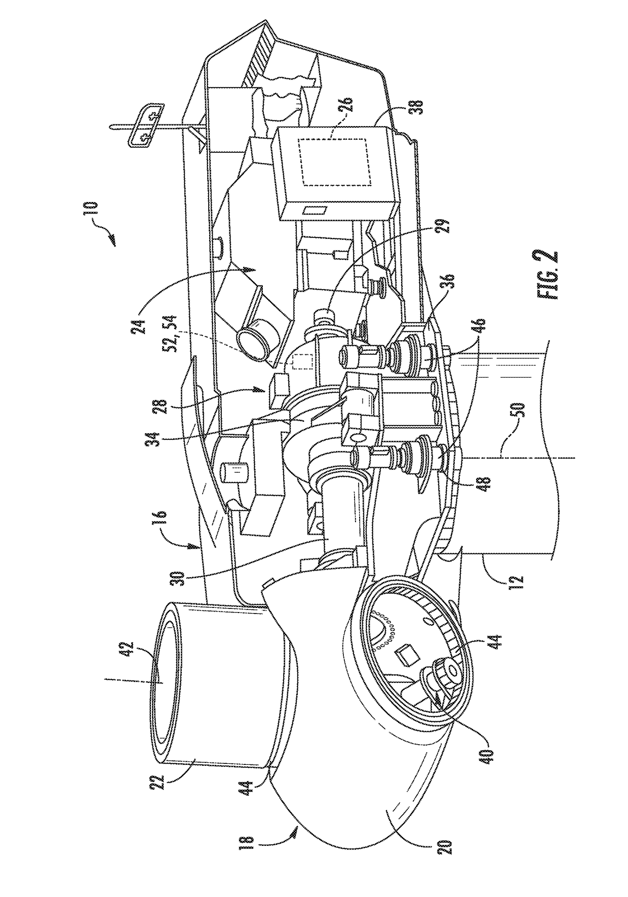
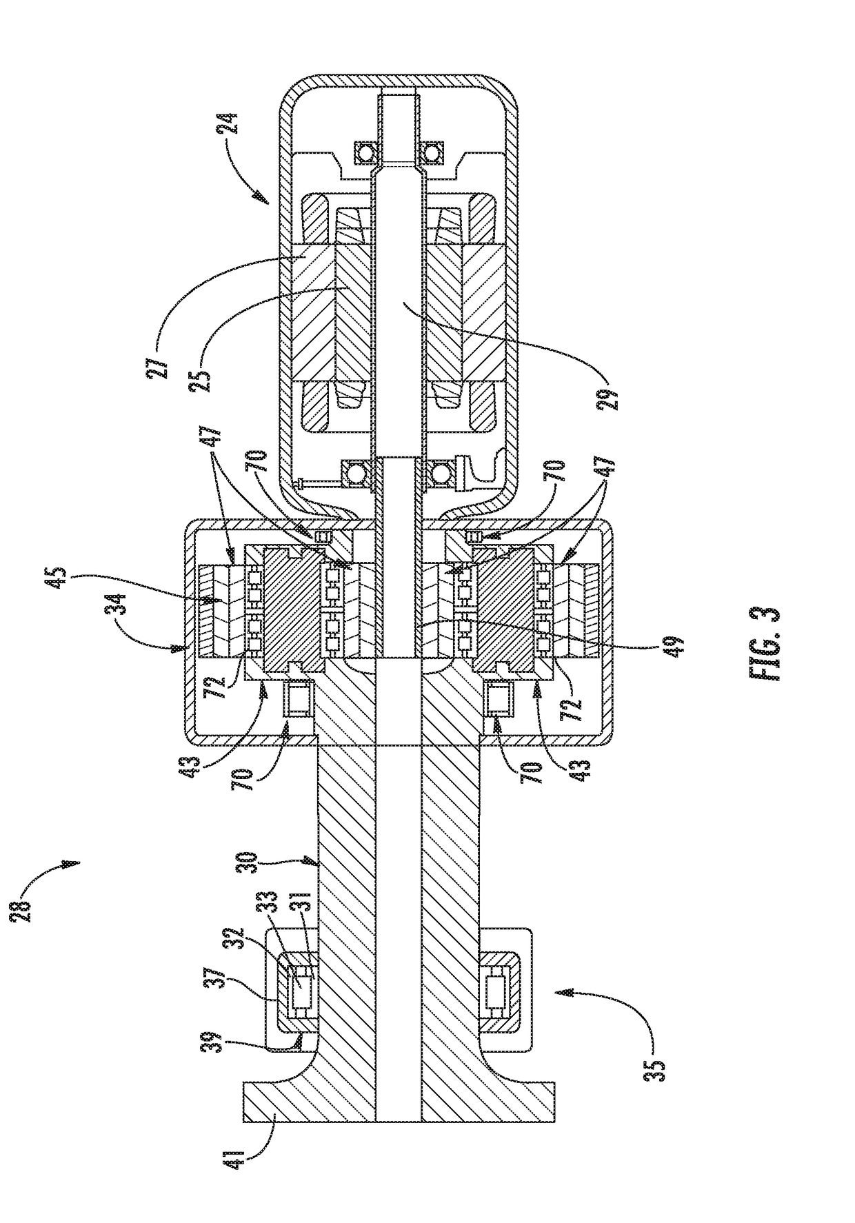
[0026]Reference now will be made in detail to embodiments of the invention, one or more examples of which are illustrated in the drawings. Each example is provided by way of explanation of the invention, not limitation of the invention. In fact, it will be apparent to those skilled in the art that various modifications and variations can be made in the present invention without departing from the scope or spirit of the invention. For instance, features illustrated or described as part of one embodiment can be used with another embodiment to yield a still further embodiment. Thus, it is intended that the present invention covers such modifications and variations as come within the scope of the appended claims and their equivalents.

[0027]Generally, the present disclosure is directed to systems and methods for detecting bearing damage in wind turbine gearboxes that utilize vibration spectrum data to trend the energy of patterns associated with bearing damage. More specifically, algorit...


PUM


Abstract

A method for detecting damage in a bearing of a wind turbine includes collecting vibration data relating to the bearing. Another step includes storing the vibration data in a memory device. The method also includes identifying a plurality of harmonics in the vibration data that are indicative of bearing damage. Further, the method includes eliminating harmonics within a specified frequency proximity to areas of high energy content representative of normal gearbox operation. Moreover, the method includes determining at least one of increases in energy or a variance of the energy within each of the remaining harmonics and calculating a damage factor of the bearing as a function of a least one of the increases in energy or the variance of the energy within each of the remaining harmonics. Accordingly, the method includes comparing the damage factor to a predetermined damage threshold, wherein a damage factor exceeding the predetermined damage threshold may be indicative of a damaged bearing.

Description

FIELD OF THE INVENTION[0001]The present disclosure relates in general to wind turbines, and more particularly to systems and methods for detecting damage in wind turbine bearings, such as low-speed bearings.BACKGROUND OF THE INVENTION[0002]Wind power is considered one of the cleanest, most environmentally friendly energy sources presently available, and wind turbines have gained increased attention in this regard. A modern wind turbine typically includes a tower, a generator, a gearbox, a nacelle, and one or more rotor blades. The rotor blades capture kinetic energy of wind using known foil principles. The rotor blades transmit the kinetic energy in the form of rotational energy so as to turn a low-speed main shaft coupling the rotor blades to a gearbox, or if a gearbox is not used, directly to the generator. For example, the generator may be coupled to the low-speed main shaft such that rotation of the shaft drives the generator. For instance, the generator may include a high-speed...

Claims


Application Information

Patent Timeline
Patent Type & Authority Applications(United States)
IPC IPC(8): F03D17/00F03D80/70G01M13/04
CPCF03D17/00F05B2260/83G01M13/045F03D80/70F05B2240/50F05B2260/80Y02E10/72
Inventor POTTER, JOSHUA JEFFREYDRESCHER, CHRISTOPHER ROBERT
Owner GENERAL ELECTRIC CO
Learn More