
System for time-shifting post-combustion co2 capture

Inactive Publication Date: 2018-11-29
BECHTEL INFRASTRUCTURE & POWER CORP
View PDF0 Cites 4 Cited by
  • Summary
  • Abstract
  • Description
  • Claims
  • Application Information

AI Technical Summary

Benefits of technology

The patent describes a method for improving the power output and net income of a power plant. It involves accumulating rich solvent from flue gas absorption during peak power levels and then regenerating it during off-peak times to improve the peak output power level. This method helps to increase the plant's ability to generate power and can lead to a significant increase in net income from power sales.

Problems solved by technology

Therefore, although the plant produces electric power while releasing limited amounts of CO2 into the atmosphere, the power generation capacity of the plant is also limited because some of the energy from the fuel has been devoted to removing and recovering CO2 from the plant exhaust.
A large power drain in the CO2 capture system is due to the heat required to regenerate the solvent.
The temperature level for regeneration is normally around 120° C. This heat is typically supplied by steam extracted from the steam cycle of the power plant and thus reduces the steam turbine power output and consequently reduces the net efficiency of the power plant.
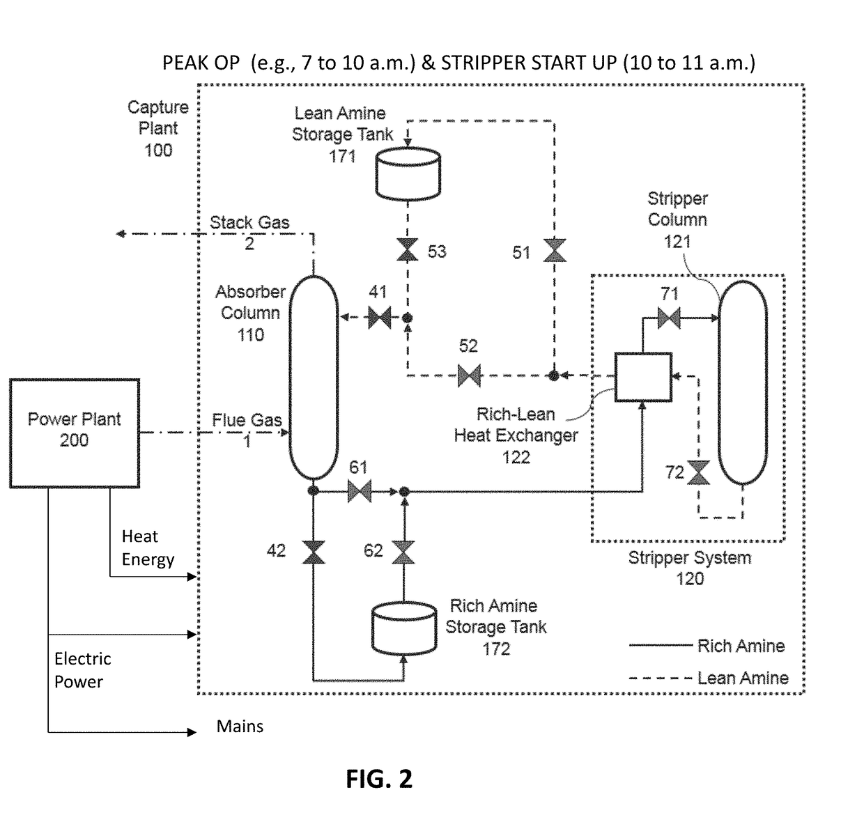
More particularly, some or all of the regeneration of gas-rich solvent produced during peak power demand times is delayed.
Advantageously, the constituent can be an undesirable constituent or set of constituents that are removed and disposed of to protect the atmosphere.

Method used


Image

  • System for time-shifting post-combustion co2 capture
  • System for time-shifting post-combustion co2 capture

Examples


Embodiment Construction

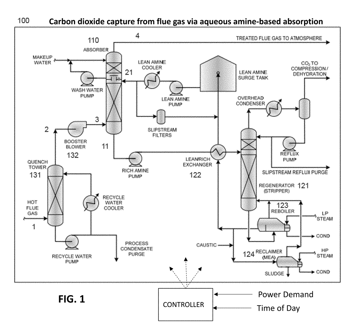
[0018]In FIG. 1, a solvent-based CO2 capture system 100 to which the present invention is advantageously applied, has a generally conventional configuration but is operated according to the invention in a manner that alters operational parameters between peak and off-peak as well as transitional (e.g., startup) conditions.

[0019]A hot flue gas stream 1 from the stack of the power plant burning a fossil fuel (not specifically shown) goes first to a quench tower 131. Quench tower 131 includes a direct-contact heat exchanger utilizing water to cool the flue gas. The circulating water that contacts the flue gas stream 1 is cooled and filtered, which can constitute a means for removing particulates that may be present in the flue gas stream. After leaving the quench tower, a cooled flue gas stream 2 is passed into a booster fan (blower) 132 to maintain the required pressure in the inlet flue gas ducts.

[0020]On exiting the blower 132, the flue gas stream 3 enters an absorber 110, for examp...


PUM

PropertyMeasurementUnit
Timeaaaaaaaaaa
Poweraaaaaaaaaa
Flow rateaaaaaaaaaa

Abstract

An undesirable constituent gas from the flue gas stream of a fossil fuel-fired power plant, especially carbon dioxide, CO2, which is a potent greenhouse gas, is captured in a recirculating solvent-based absorption operation such as with an amine-based solvent. The solvent is exposed to flue gases for capture of the undesirable constituent, then heated to extract captured undesirable constituent for disposal, also regenerating the gas-rich solvent to gas-lean solvent for re-use. Absorption is continuous and uses the lean solvent at a rate proportional to the combustion rate. Solvent regeneration and its associated power loading are deferred and time-shifted to periods when the plant is operating below its peak power level. At high or peak power levels, rich solvent from absorption is accumulated in a storage vessel. At off-peak times, rich solvent accumulated in the storage vessel is regenerated together with rich solvent from concurrent absorption. Deferring regeneration to off peak (low price) times improves the peak (high price) output power level of which the plant is capable, and considerably increases revenue.

Description

FIELD OF THE INVENTION[0001]This disclosure relates to apparatus and techniques for removal of an undesirable constituent gas, particularly carbon dioxide, a potent greenhouse gas, from stack (flue) gases, especially for a fossil fuel-fired electric power generation plant.BACKGROUND OF THE INVENTION[0002]The invention facilitates efficient and cost-effective carbon dioxide removal by implementation of a removal technology that includes deferring the regeneration of used solvent (i.e., CO2 rich solvent that has been exposed to flue gases) during times of peak demand for electricity. The stored solvent that would be regenerated concurrently with exposure to flue gases in a base loaded system is regenerated instead during off-peak demand periods. Among other results, the peak electric power output of the plant is increased and substantial cost savings are realized compared to base loaded carbon dioxide removal operations.[0003]Carbon dioxide (CO2) constitutes a large fraction of the gr...

Claims


Application Information

Patent Timeline
IPC IPC(8): B01D53/34B01D53/62B01D53/52B01D53/14B01D53/78B01D53/96
CPCB01D53/346B01D53/62B01D53/526B01D53/1475B01D53/78B01D53/96B01D2252/20431B01D2252/20405B01D2252/20426B01D2252/20489B01D2252/20421B01D2252/20484B01D2258/0283B01D53/1412B01D53/1425B01D2252/204Y02A50/20Y02C20/40
Inventor ELLIOTT, WILLIAM R.GULEN, SEYFETTIN C.
Owner BECHTEL INFRASTRUCTURE & POWER CORP
Learn More