
Detector for optically detecting at least one object

a detector and optical detection technology, applied in the field of detectors, can solve the problems of inherently limited use of large area sensors in the use of fip measurement principles, limited choice of materials for fip-detector and psd-detector, and inability to meet the requirements of fip and/or psd detectors, etc., and achieve the effect of low requirements and low technical effor

Inactive Publication Date: 2018-11-15
TRINAMIX GMBH
View PDF0 Cites 39 Cited by
  • Summary
  • Abstract
  • Description
  • Claims
  • Application Information

AI Technical Summary

Benefits of technology

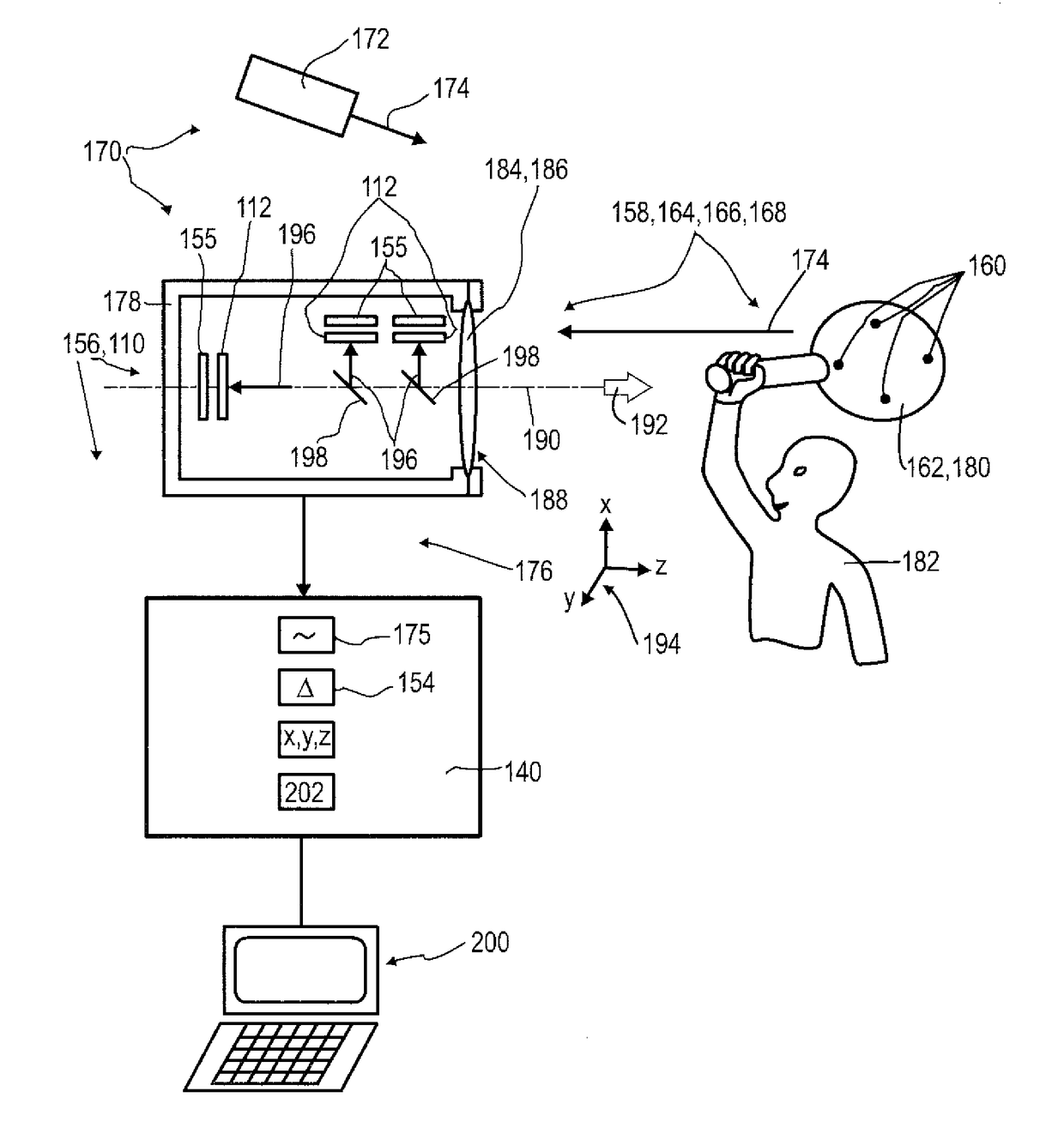
The present invention relates to a detecter that can easily distinguish between different objects or parts within the same field of view. This is achieved by combining longitudinal and transversal sensor signals acquired at different modulation frequencies. Additionally, the detecter uses a (semi-)transparent PSD device, which allows for a simultaneous 3D determination of multiple objects or parts. The technical effects include improved performance in terms of miniaturization, robustness, determination time, determination accuracy, and cost-effectiveness.

Problems solved by technology

Despite the advantages implied by the above-mentioned devices and detectors, several technical challenges remain.
Still, large area sensors in many cases are inherently limited in the use of the FiP measurement principle, specifically in case more than one light spot is to be investigated simultaneously.
Semitransparency, however, restricts the options of choice for both FiP-detector and PSD-detector materials.
Thus, transparency of FiP and / or PSD detectors remains a technical challenge.
A further challenge using FiP or PSD detectors is the detector area or active area.
This area, however, may cause noise problems, specifically when the tetralateral conductivity concept is employed to build a PSD.
This often results in poor signal-to-noise-ratios and slow detector response times due to the large capacitance in conjunction with the series resistance of the detector.
Even though these concepts allow for an efficient determination of 3D coordinates and even though these concepts are significantly superior to known 3D sensing concepts such as triangulation, some challenges remain, specifically regarding the need for calculating power and resources, as well as increasing the efficiency.
However, this kind of PSD device is not adapted for 3D-sensing such that further development is required to provide an optical detector well-suited for this purpose.
This discussion of known concepts, such as the concepts of several of the above-mentioned prior art documents, clearly shows that some technical challenges remain.
Further, complexity of the optical systems still remains an issue which may be addressed.

Method used


Image

  • Detector for optically detecting at least one object
  • Detector for optically detecting at least one object
  • Detector for optically detecting at least one object

Examples


working examples

[0495]I. Production of the Colored Samples

[0496]I.1 PMMA as matrix

[0497]1000.00 g of polymethyl methacrylate (PMMA 6N clear, available from Röhm GmbH, Germany) were predried at a maximum temperature of 90° C. for 4 hours and then mixed with 0.02 weight % of a Fluorescent colorant X (see Table 2) in a Turbula Fuchs mixer for 20 min. The homogenous mixture was extruded on a Twin Screw 25 mm extruder from Collin, Germany, six heating zones (cold, 150° C., 195° C., 200° C., 200° C., 200° C., 200° C.) at a maximum temperature of 200° C. The extrudate was granulated in a granulator (Scheer, Stuttgart). The granulate was dried at a maximum temperature of 90° C. for 4 hours and then processed to colored samples (30 mm×55 mm×approx. 1.2 mm) using a Boy Injection Molding Machine (Boy 30A from Dr. Boy GmbH, Neustadt, Germany) or a Klöckner Ferromatik FM 40 (from Klöckner, Germany). The mouldings obtained were packed up in an oxygen free plastic bag with a vacuum pack machine after drying.

TABLE...


PUM


Abstract

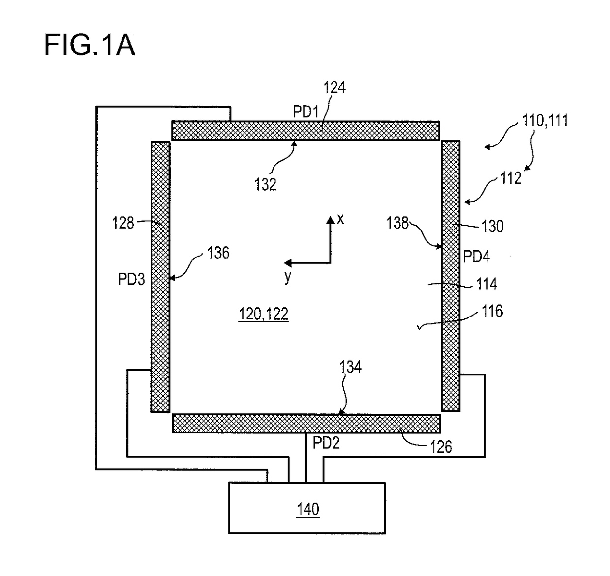
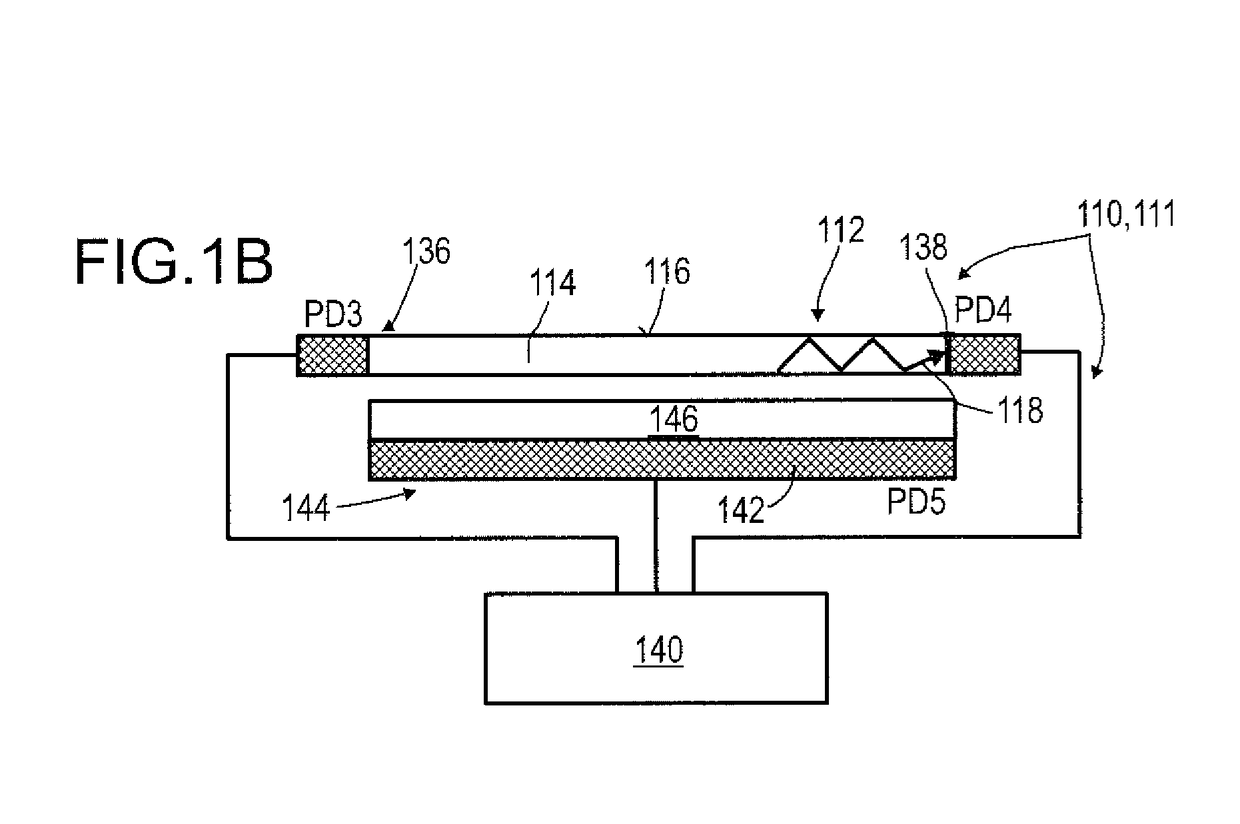
A detector, for determining a position of at least one object, includes: at least one longitudinal optical sensor for determining a longitudinal position of at least one light beam traveling from the object to the detector, at least one transversal optical sensor determining at least one transversal position of the at least one light beam, including at least one fluorescent waveguiding sheet forming a transversal sensitive area, at least two photosensitive elements located at at least two edges of the fluorescent waveguiding sheet capable of detecting fluorescence light guided from the light spot towards the photosensitive elements by the fluorescent waveguiding sheet and capable of generating transversal sensor signals; and at least one evaluation device configured to determine at least one longitudinal coordinate of the object by evaluating the longitudinal sensor signals, and to determine at least one transversal coordinate of the object by evaluating the transversal sensor signals.

Description

FIELD OF THE INVENTION[0001]The invention relates to a detector, a detector system and a method for determining a position of at least one object. The invention further relates to a human-machine interface for exchanging at least one item of information between a user and a machine, an entertainment device, a tracking system, a camera, a scanning system and various uses of the detector device. The devices, systems, methods and uses according to the present invention specifically may be employed for example in various areas of daily life, gaming, traffic technology, production technology, security technology, photography such as digital photography or video photography for arts, documentation or technical purposes, medical technology or in the sciences. However, other applications are also possible.PRIOR ART[0002]A large number of optical sensors and photovoltaic devices are known from the prior art. While photovoltaic devices are generally used to convert electromagnetic radiation, ...

Claims


Application Information

Patent Timeline
IPC IPC(8): G01S5/16G06F3/03G01S7/481G01S17/46G01S17/66
CPCG01S5/16G06F3/0304G01S7/4816G01S17/46G01S17/66G06F3/0308G06F3/042
Inventor SEND, ROBERTBRUDER, INGMARLUNGENSCHMIED, CHRISTOPH
Owner TRINAMIX GMBH
Learn More