
Device and method for processing audio signal

a technology of audio signal and device, applied in the direction of signal processing, stereophonic communication headphones, electrical transducers, etc., can solve the problems of deteriorating the performance of accurately representing the position of individual sound objects in an audio scene, and achieve the effects of preventing deterioration of sound localization, reducing computational complexity, and reducing nois

Active Publication Date: 2018-11-08
GAUDI AUDIO LAB
View PDF4 Cites 7 Cited by
  • Summary
  • Abstract
  • Description
  • Claims
  • Application Information

AI Technical Summary

Benefits of technology

This patent aims to provide high-quality binaural sound with low computational complexity. It also aims to prevent sound localization and degradation of sound quality during binaural rendering. Additionally, it aims to implement rendering on an HOA signal that improves sound image localization with low computational complexity.

Problems solved by technology

However, while the HOA has an advantage of reproducing the entire audio scene, it has a disadvantage in that the performance of accurately representing positions of individual sound objects within an audio scene is deteriorated.

Method used


Image

  • Device and method for processing audio signal
  • Device and method for processing audio signal
  • Device and method for processing audio signal

Examples


first embodiment

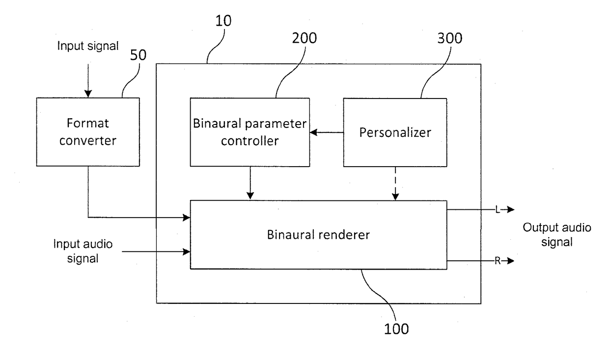
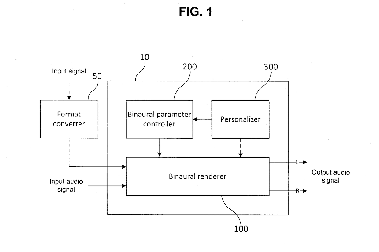
[0109]A binaural renderer 100A according to the present invention performs binaural rendering on the ambisonic signal using a B2C conversion and a C2P conversion. The C2P conversion refers to a conversion from a channel signal to a binaural signal. The binaural renderer 100A may receive head tracking information reflecting movement of a head of a listener, and may perform matrix multiplication for rotation transform of the B-format signal based on the information. As described above, the binaural renderer 100A may determine the B2C conversion matrix based on the rotation transform information. The B-format signal is converted to a virtual channel signal or an actual loudspeaker channel signal using the B2C conversion matrix. Next, the channel signal is converted to the final binaural signal through the C2P conversion.

second embodiment

[0110]Meanwhile, a binaural renderer 100B according to the present invention may perform binaural rendering on the ambisonic signal using the B2P conversion. The B2P conversion refers to a direct conversion from a B-format signal to a binaural signal. That is, the binaural renderer 100B directly converts the B-format signal into a binaural signal without a process of converting it into a channel signal.

[0111]FIG. 4 illustrates a process in which a binaural signal is obtained from a signal recorded through a binaural microphone array. A binaural microphone array 30 may be composed of 2N microphones 32 existing on a horizontal plane. According to an embodiment, each microphone 32 of the binaural microphone array 30 may be arranged with a pinna model depicting the shape of the external ear. Accordingly, each microphone 32 of the binaural microphone array 30 can record an acoustic signal as a signal to which an HRTF is applied. The signal recorded through the pinna model is filtered by ...


PUM


Abstract

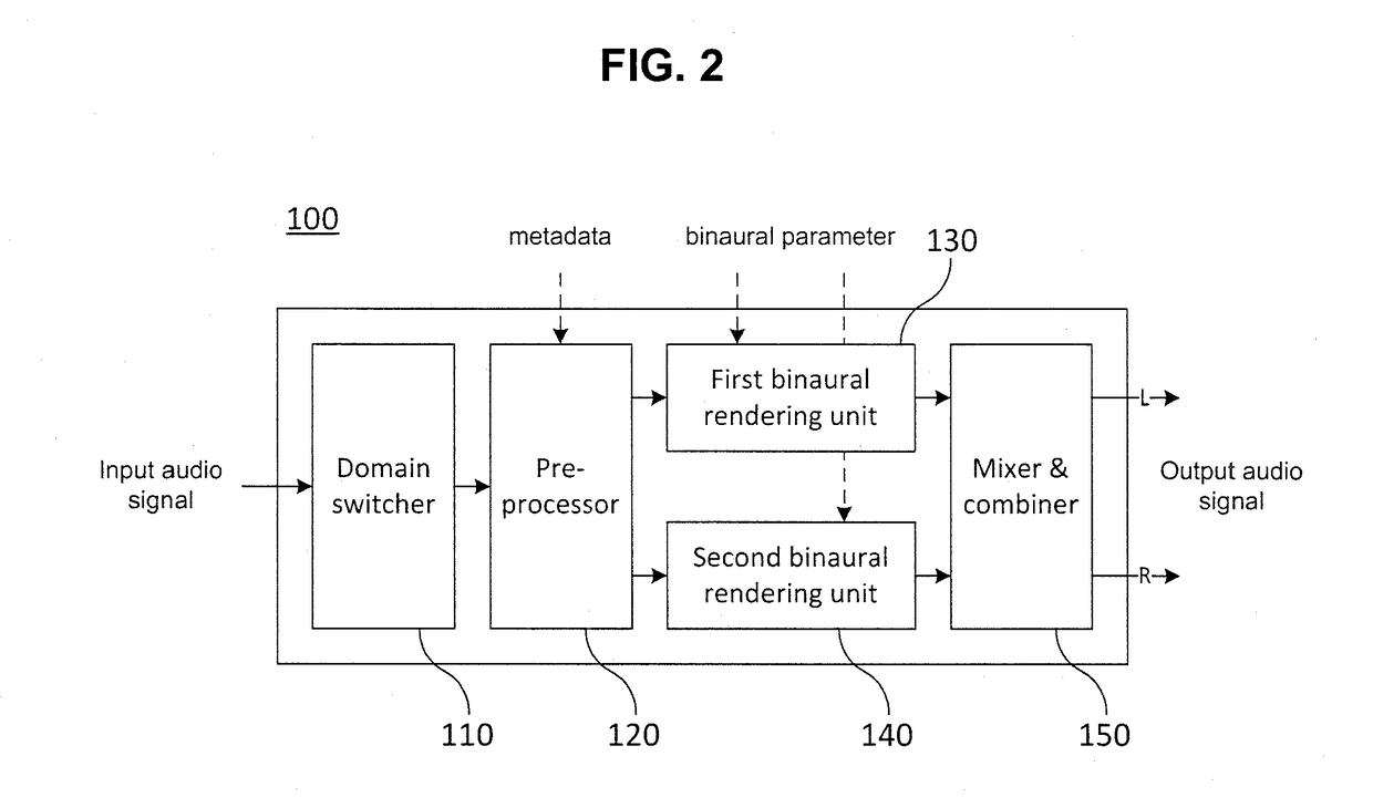
The present invention relates to an apparatus and a method for processing an audio signal, and more particularly, to an apparatus and a method for efficiently rendering a higher order ambisonics signal. To this end, provided are an audio signal processing apparatus, including: a pre-processor configured to separate an input audio signal into a first component corresponding to at least one object signal and a second component corresponding to a residual signal and extract position vector information corresponding to the first component from the input audio signal; a first rendering unit configured to perform an object-based first rendering on the first component using the position vector information; and a second rendering unit configured to perform a channel-based second rendering on the second component and an audio signal processing method using the same.

Description

CROSS-REFERENCE TO RELATED APPLICATIONS[0001]This application claims the benefit under 35 U.S.C. § 120 and § 365(c) to a prior PCT International Application No. PCT / KR2017 / 000633, filed on Jan. 19, 2017, which claims the benefit of Korean Patent Application No. 10-2016-0006650, filed on Jan. 19, 2016, the entire contents of which are incorporated herein by reference.TECHNICAL FIELD[0002]The present invention relates to an apparatus and a method for processing an audio signal, and more particularly, to an apparatus and a method for efficiently rendering a higher order ambisonics signal.BACKGROUND ART[0003]3D audio collectively refers to a series of signal processing, transmitting, coding, and reproducing technologies which provide another axis corresponding to a height direction to a sound scene on a horizontal surface (2D) which is provided from surrounding audio of the related art to provide sound having presence in a three dimensional space. Specifically, in order to provide 3D au...

Claims


Application Information

Patent Timeline
Patent Type & Authority Applications(United States)
IPC IPC(8): H04S7/00H04S3/00H04R5/02
CPCH04S7/303H04S3/008H04R5/02H04S2400/01H04S2420/11H04S2400/11H04S2420/01H04R2201/401H04R2430/20H04S3/00H04S2400/03H04S2420/03H04S2420/07H04R5/033
Inventor SEO, JEONGHUNLEE, TAEGYUOH, HYUN OH
Owner GAUDI AUDIO LAB
Learn More