
Three dimensional auxetic structure, manufacturing method and tooling

a manufacturing method and auxetic technology, applied in the direction of machines/engines, fuselage bulkheads, synthetic resin layered products, etc., can solve the problem of increasing the size in the transverse dimension, and achieve the effect of high impact energy absorption

Active Publication Date: 2018-11-01
AIRBUS OPERATIONS SL
View PDF0 Cites 11 Cited by
  • Summary
  • Abstract
  • Description
  • Claims
  • Application Information

AI Technical Summary

Benefits of technology

The patent describes a new type of sandwich panel that can change its shape when controlled. This makes it useful for creating lightweight objects that can absorb impact energy, damp acoustics, and carry loads. The panel's shape is controlled by adjusting the distance between its walls, and a specific tool is used to fold the walls into position. This is particularly useful for composite materials, where a resin curing or injection process is typically required. Overall, this patent provides a new way to create efficient and flexible structures that can change shape when needed.

Problems solved by technology

Therefore, applying a unidirectional tensile force to auxetic material results in an increase in size in the transverse dimension.

Method used


Image

  • Three dimensional auxetic structure, manufacturing method and tooling
  • Three dimensional auxetic structure, manufacturing method and tooling
  • Three dimensional auxetic structure, manufacturing method and tooling

Examples


first embodiment

[0040]FIG. 5 discloses a sectional view of a sandwich panel comprising a first embodiment having a three-dimensional auxetic core structure according to an embodiment of the invention in which the structure is located with the hollow direction of the cells (2) perpendicular to the upper and lower sandwich panels (10). When these sandwich panels are subjected to compression forces normal to the panels (10), the sandwich core tends to contract on the other two directions, generating a condensation of material on the impact point. This condensation of material provides additional capability to resist impact and penetration normal to the sandwich panel (10).

[0041]Another advantage of this core is that the failure of the cell walls (3) is more progressive and transmits deformation to a larger part of the surrounding structure, so the cell walls are able to absorb more energy than the case when the cell walls (3) are not folded. On the conventional core without folded cell walls (3), they...

second embodiment

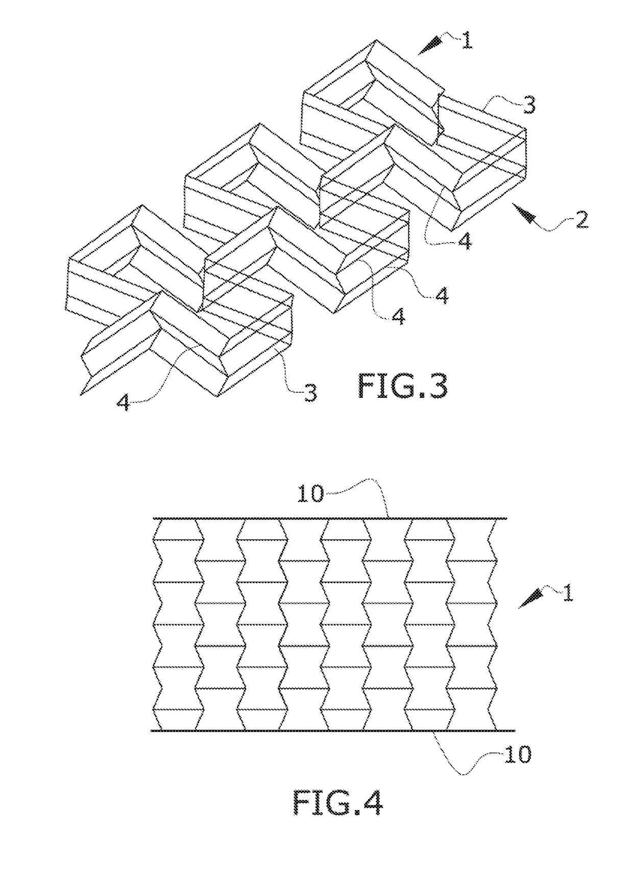
[0043]FIG. 4 discloses a sectional view of a sandwich panel comprising a second embodiment having a three-dimensional auxetic structure according to an embodiment of the invention in which the structure is located with the hollow direction of the cells (2) parallel to the upper and lower sandwich panels (10). This embodiment provides the additional advantage of not generating closed cells in between the sandwich panels allowing a better drainage of possible water ingested by the sandwich core.

[0044]FIGS. 6, 7 and 8 show possible applications to an aircraft:

[0045]Fuselage and empennage skins shielding against engine debris and other impact threats.

[0046]Lifting surface LE shielding against bird and other impact threats.

[0047]Sandwich can be just a panel surrounding the perimeter of aero dynamic profile or can cover the full cavity of the profile section or part of the profile section (LE, box or TE). The proposed core is able to adapt to thickness variations of the sandwich due to th...


PUM


Abstract

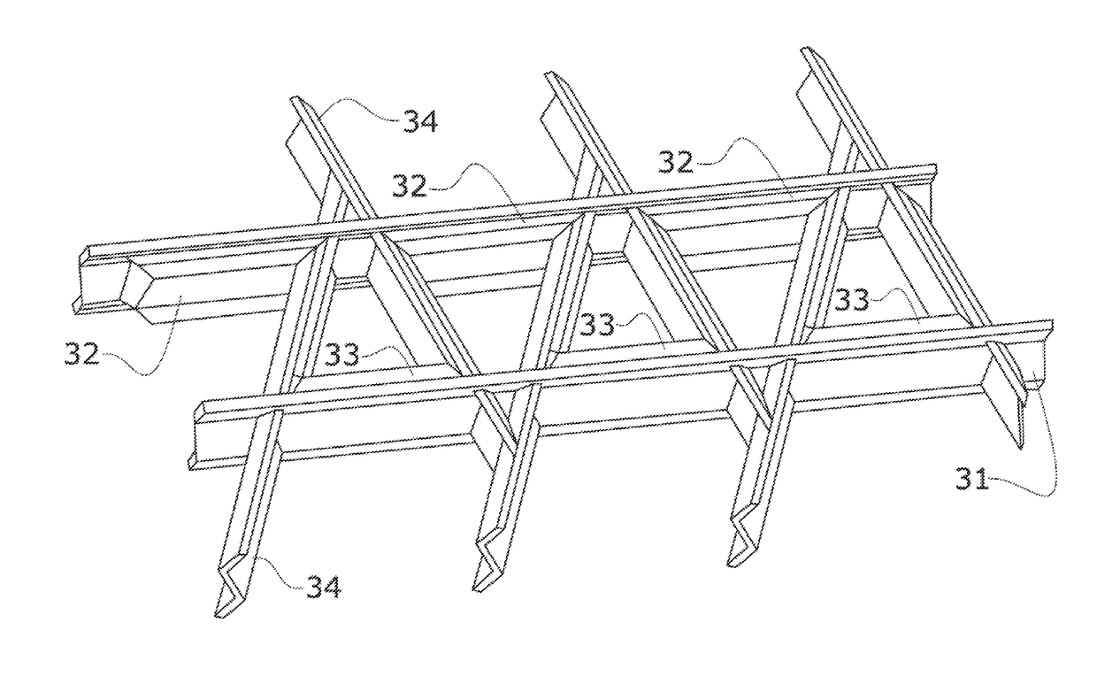
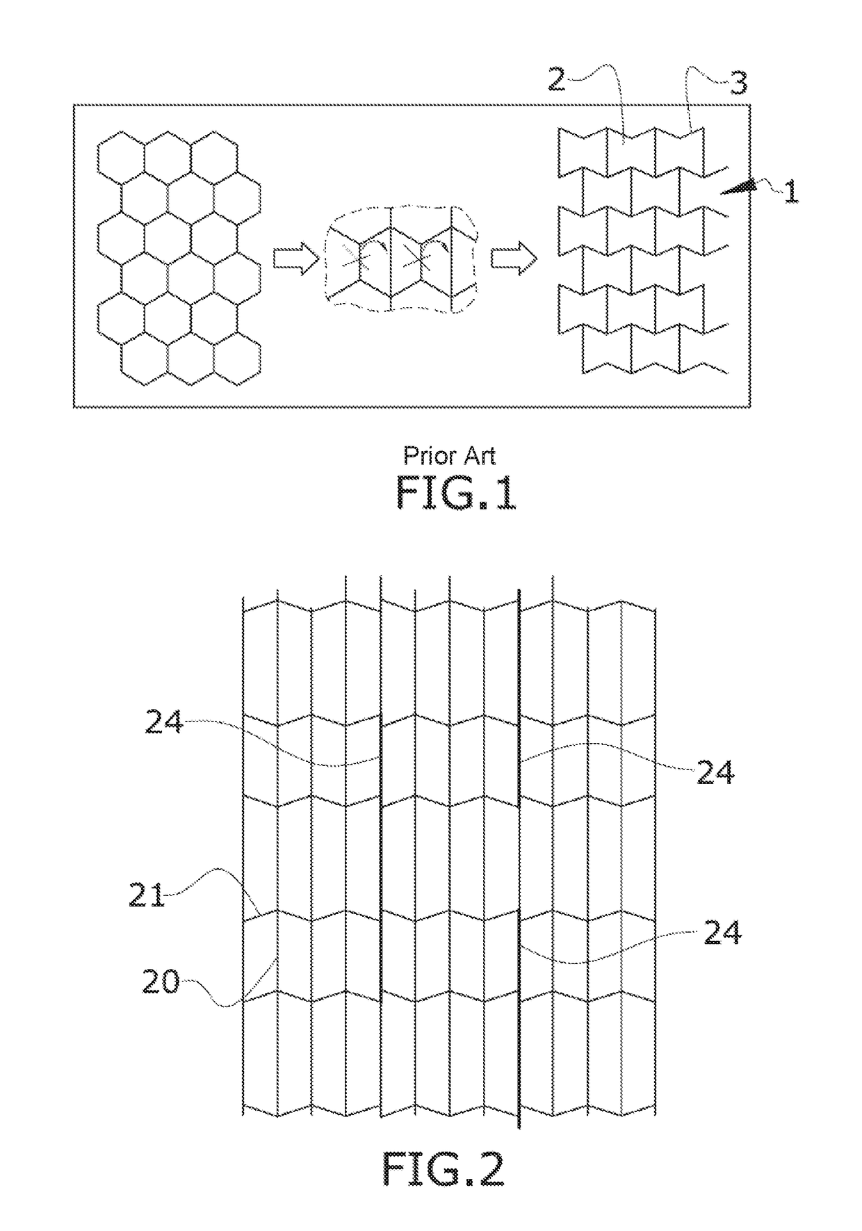
A three-dimensional auxetic structure, comprising a plurality of adjoining hollow cells, each hollow cell having cell walls and a transversal cross section of the plurality hollow cells following a two-dimensional auxetic pattern, each cell wall comprising folding lines parallel to a plane containing the auxetic pattern such that peaks and valleys are defined in the cell walls and the cell walls being foldable along the folding lines.

Description

CROSS-REFERENCES TO RELATED APPLICATIONS[0001]This application claims the benefit of the European patent application No. 17382222.2 filed on Apr. 26, 2017, the entire disclosures of which are incorporated herein by way of reference.FIELD OF THE INVENTION[0002]The present invention is related to a three-dimensional auxetic structure that can be made from a sheet material or by 3D printing. Specifically, it refers to a cellular material for a sandwich panel used in aircraft construction, shipbuilding, and other branches of industry and its associated manufacturing method and mold.BACKGROUND OF THE INVENTION[0003]Conventional materials found in nature have positive Poisson ratio, they get thinner when stretched and fatter when compressed, following the Poisson ratio equation:vyx=-transversestrainaxialstrain=-ɛxɛy[0004]Accordingly, Poisson's ratio is defined as the negative of the transverse strain divided by the longitudinal strain.[0005]There are materials or structure geometries conf...

Claims


Application Information

Patent Timeline
IPC IPC(8): B64C1/12B29C53/04B32B3/12B32B15/01B32B27/08B64C3/26B64C11/20
CPCB64C1/12B29C53/04B32B3/12B32B15/01B32B27/08B64C3/26B64C11/20B33Y80/00B29K2101/12B29L2031/082B29L2031/3082B33Y10/00B32B2250/03B32B2250/40B32B2605/18B21D5/16B29D99/0089B31D3/02B32B15/08B32B27/06B32B27/12B29K2995/0002B29K2995/0091B29K2995/0094A43B1/0009B31D3/0207B64C2001/0072B64C2027/4736F05D2250/182F05D2250/131F05D2250/183B64C11/26F01D5/147F01D11/00F01D21/045F01D21/14F05D2220/36F05D2250/283F05D2230/54F05D2250/132A43B13/02A43B13/14B64D2033/022B64D2045/009Y02T50/40Y02T50/60F01D5/282
Inventor VELEZ DE MENDIZ BAL ALONSO, IKERMARTINO GONZ LEZ, ESTEBANAPELLANIZ DE LA FUENTE, DAVIDPARRA RUBIO, ALFONSOMOYA SANZ, ELENA
Owner AIRBUS OPERATIONS SL
Learn More