Method for operating a medical-optical display system

a display system and optical display technology, applied in the field of optical display system operation, to achieve the effect of little time variability, little time variability, and little time variability

Active Publication Date: 2018-10-25
CARL ZEISS MEDITEC AG
View PDF0 Cites 4 Cited by
  • Summary
  • Abstract
  • Description
  • Claims
  • Application Information

AI Technical Summary

Benefits of technology

[0026]In order to obtain a sufficiently large contiguous area with little time variability and suitable size for superimposing the image data record, it may be advantageous for individual contiguous areas with little time variability to be merged into a larger contiguous area with little time variability by image processing, wherein the larger contiguous area with little time variability is then specified as the at least one region with little activity.

Problems solved by technology

However, these approaches are disadvantageous in that there has to explicitly be tool recognition (in the extreme case, the algorithm must be newly parametrized for each new tool set).

Method used


Image

  • Method for operating a medical-optical display system
  • Method for operating a medical-optical display system
  • Method for operating a medical-optical display system

Examples


Embodiment Construction

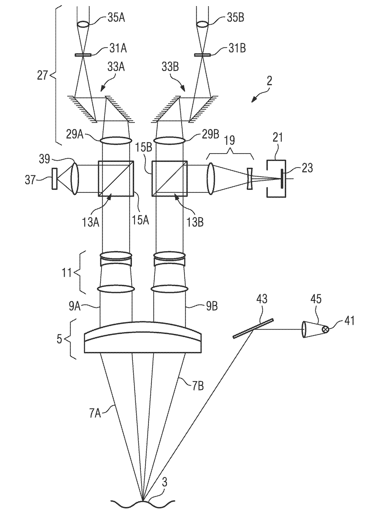
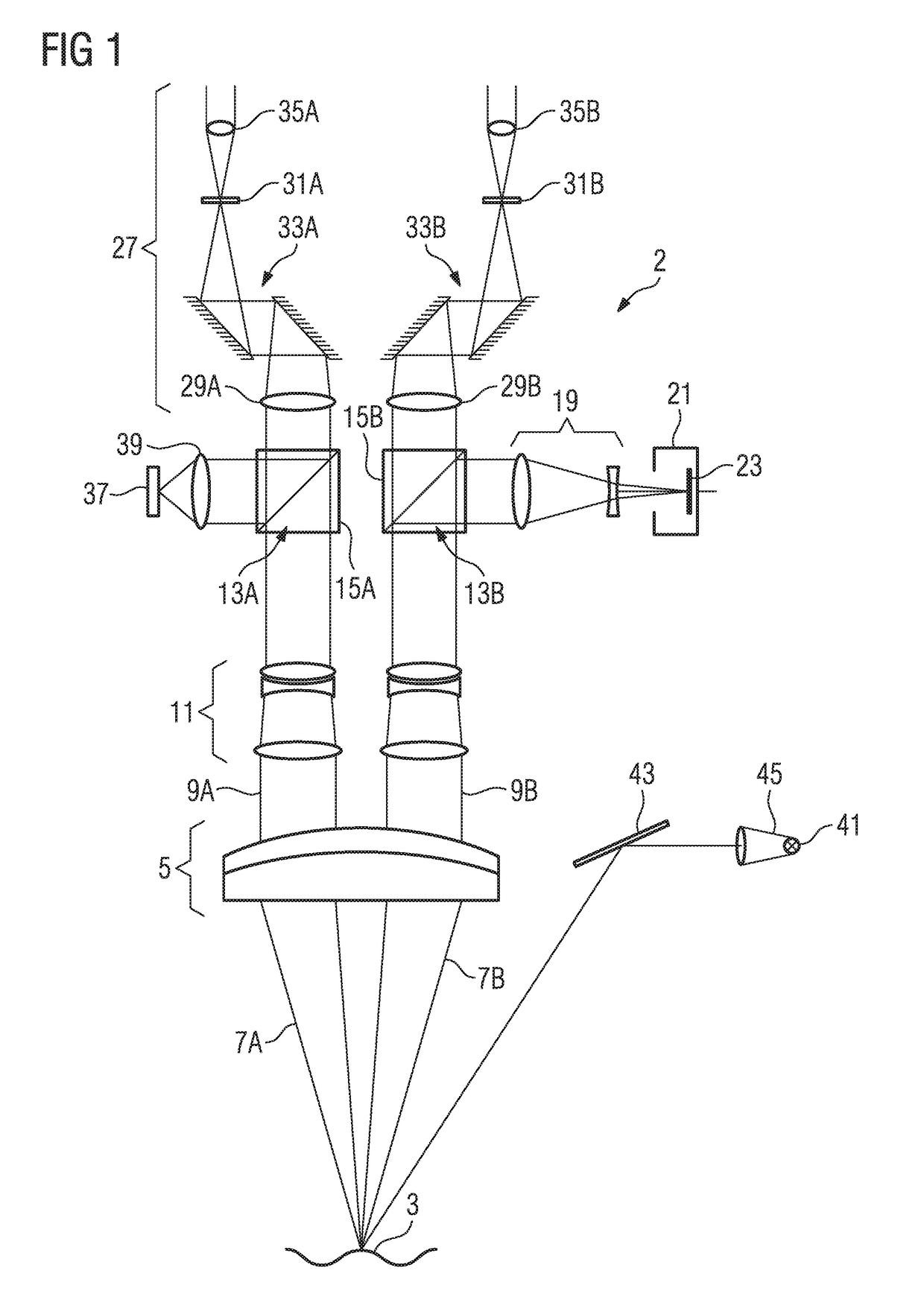
[0052]Reference is made to FIG. 1, which schematically illustrates the structure of an operating microscope. In the present exemplary embodiment, the medical-optical display system is a part of the operating microscope 2.

[0053]An operating microscope 2 is understood to be a microscope that is used in minimally invasive surgery and microsurgery. It has a comparatively low magnification (approximately 6× to 40×) and, as a rule, provides a three-dimensional image. The magnification goes beyond that of magnifying spectacles. In the medical field, it is used in almost all lines of surgery.

[0054]The operating microscope 2 shown in FIG. 1 comprises an objective 5 that should face an object field 3, said objective, in particular, being able to be embodied as an achromatic or apochromatic objective. In the present exemplary embodiment, the objective 5 consists of two partial lenses that are cemented to one another and form an achromatic objective. The object field 3 is arranged in the focal ...


PUM


Abstract

A method for operating a medical-optical display system for displaying an object image of an observed object is made available, said object image having been obtained by means of a medical-optical observation apparatus wherein the medical-optical display system comprises a data superimposition unit for superimposing data of at least one image data record into the object image. The method comprises the following steps: determining at least one region with little activity within the object image and superimposing the at least one image data record into the at least one region with little activity.

Description

[0001]The present application claims priority to German Application No. 10 2017 108 371.5 filed Apr. 20, 2017, the disclosure of which is hereby incorporated by reference herein in its entirety.BACKGROUND OF THE INVENTIONField of the Invention[0002]The invention relates to a method for operating a medical-optical display system having a data superimposition apparatus. Further, the invention relates to a computer program product for carrying out such a method and to a medical-optical display system having a data superimposition apparatus.Description of Related Art[0003]A medical-optical observation apparatus in which an image data record with additional information items is mirrored into an image provided by the medical-optical observation apparatus by means of a device for mirroring-in data is known from DE 10 2014 210 150 A1.[0004]In general, the position in the image into which the image data record is mirrored is set by the device for superimposing data, without reference being m...

Claims


Application Information

Patent Timeline
Patent Type & Authority Applications(United States)
IPC IPC(8): G02B23/10A61B1/04A61B1/00G02B21/00A61B90/00G06T7/00
CPCG02B23/10A61B1/04A61B1/0005G02B21/0012A61B90/361G06T7/0012A61B2034/2055A61B2090/3784A61B90/08A61B90/20G16H30/40A61B3/0008A61B3/132G02B21/20G02B21/22G02B21/364G02B21/365G06T2207/10021G06T2207/10056G06T7/254A61B1/00009A61B90/30G06T11/60
Inventor SAUR, STEFANKASBACH, CHRISTOPHER
Owner CARL ZEISS MEDITEC AG
Why Eureka
Try Eureka