Gasket and manufacturing method thereof

a gasket and manufacturing method technology, applied in the direction of engine seals, packaging, sealing arrangements, etc., can solve the problems of poor sealing properties, high manufacturing costs, and essentially required maintenance, and achieve high thermal conductivity, improve cooling efficiency of a target portion, and reduce manufacturing costs

Active Publication Date: 2018-10-25
ISHIKAWA GASKET CO LTD
View PDF18 Cites 5 Cited by
  • Summary
  • Abstract
  • Description
  • Claims
  • Application Information

AI Technical Summary

Benefits of technology

[0005]The present invention has been made in view of the above-described problems and an object of the present invention is to provide a gasket capable of improving cooling efficiency with a simpler configuration while keeping performance of a gasket and a gasket manufacturing method.
[0008]According to the present invention, the annular portion and the main body portion are formed by the metal wire woven fabric and the high thermal conduction region is formed by entangling the first metal wires to be joined together and weaving the second metal wires each having higher thermal conductivity than the first metal wires. Therefore, since the compressive stress generated by the metal wire woven fabric is used for the gasket, it is possible to improve cooling efficiency of a target portion by the high thermal conduction region while keeping the sealing performance. Since the high thermal conduction region can be formed only by weaving the second metal wires together with the first metal wires, it is advantageous to decrease the number of components or simplify the manufacturing process and to form the high thermal conduction region at an arbitrary position.
[0009]In this way, according to the present invention, it is possible to improve cooling efficiency with a simpler configuration while keeping performance of a gasket compared to a conventional gasket using a metal plate having high thermal conductivity.

Problems solved by technology

Incidentally, a gasket which is formed of a material having a high thermal conductivity such as copper, copper alloy, and graphite is known in addition to the gasket disclosed in JP 2014-111948 A. The gasket which is formed of a material having a high thermal conductivity is excellent in cooling efficiency compared to a gasket formed of stainless steel, but has various problems in which a sealing property is poor, a manufacturing cost is high, and maintenance is essentially required.
However, since there is a need to combine a plurality of members, another problem arises wherein the number of components increases or the manufacturing process becomes complicated.
Further, since it is difficult to apply the same structure to a small hole such as a water hole or oil hole having a small opening diameter compared to the combustion chamber hole, there is a problem that only the cooling efficiency of a specific position can be improved.

Method used


Image

  • Gasket and manufacturing method thereof
  • Gasket and manufacturing method thereof
  • Gasket and manufacturing method thereof

Examples


first embodiment

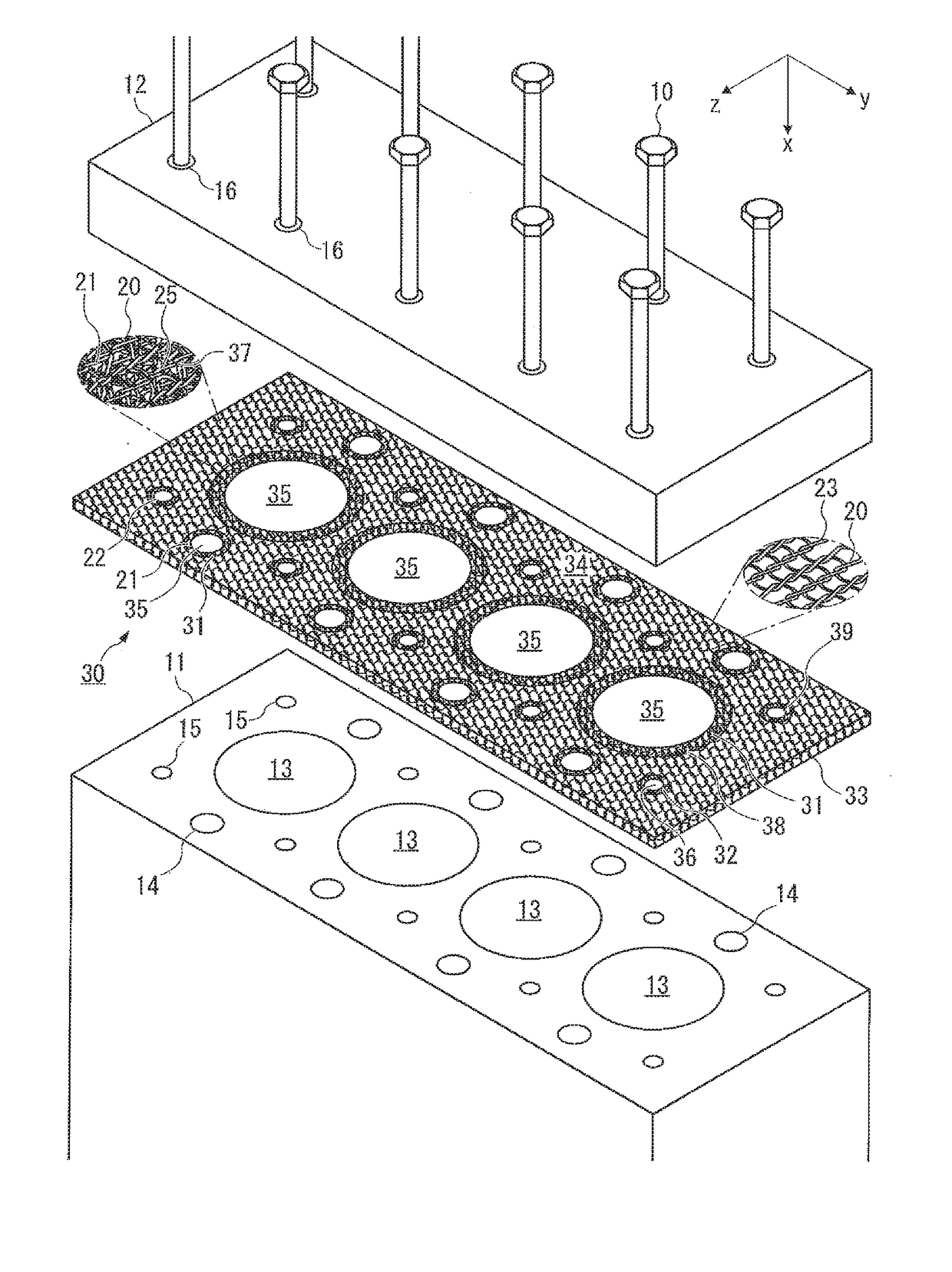
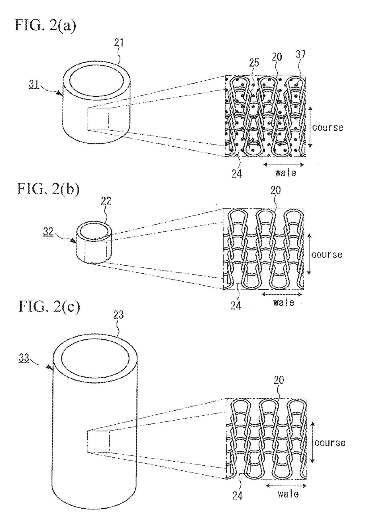
[0015]As illustrated in FIG. 1, a gasket 30 of a first embodiment is a cylinder head gasket which is sandwiched between a cylinder block 11 and a cylinder head 12 and is fastened by bolts 10.

[0016]The cylinder block 11 is provided with four cylinder bores 13 which correspond to seal target holes and a water / oil holes 14 which are water holes for a water jacket formed on the outer periphery of the cylinder bore 13 or oil holes for a lubricating oil. Pistons (not illustrated) are assembled inside the cylinder bores 13 so as to be movable in the vertical direction. In the cylinder block 11, four bolt holes 15 are formed for one cylinder bore 13 at the outer periphery of the cylinder bore 13.

[0017]An injector or intake / exhaust valve (not illustrated) is assembled to the cylinder head 12 and a bolt holes 16 corresponding to the bolt holes 15 of the cylinder block 11 are penetrated therethrough.

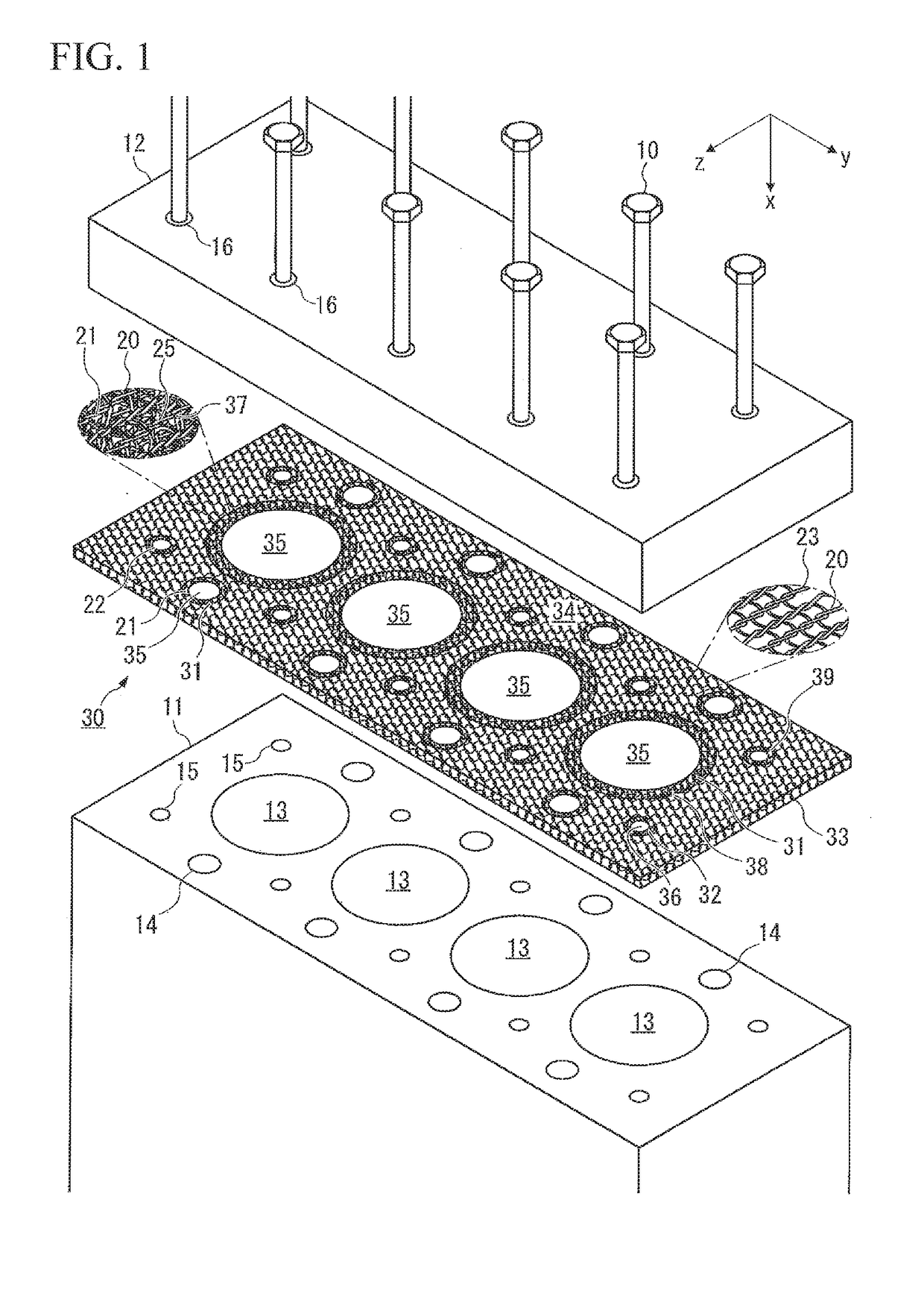
[0018]The gasket 30 is formed by metal wire woven fabrics 21 to 23 obtained by weaving a first ...

second embodiment

[0050]As illustrated in FIG. 4, in the gasket 30 of a second embodiment, the first annular portion 31, the second annular portion 32, and the main body portion 33 have different compressive stresses in the x direction while the gasket 30 is sandwiched between the cylinder block 11 and the cylinder head 12 and is fastened by the bolts 10.

[0051]The compressive stresses for the first annular portion 31, the second annular portion 32, and the main body portion 33 are generated when the tightening force (fastening force) generated by the bolts 10 becomes equal to or larger than the degree that the plate surface 34 becomes familiar to the seat surfaces of the cylinder block 11 and the cylinder head 12 (the degree that the plate surfaces 34 thereof contact the seat surfaces of the cylinder block 11 and the cylinder head 12 without gaps).

[0052]Specifically, in the embodiment, the first annular portion 31, the second annular portion 32, and the main body portion 33 have different volume dens...


PUM


Abstract

An object of the present invention is to provide a gasket capable of improving cooling efficiency with a simpler configuration while keeping performance of the gasket and a manufacturing method thereof. A gasket includes a first annular portion which is formed by a metal wire woven fabric obtained by weaving a first metal wire and includes a seal target hole and a main body portion which is in contact with an outer peripheral edge of the first annular portion, in which the first metal wire forming the first annular portion and the first metal wire forming the main body portion are entangled with each other and a second metal wire is woven together with the first metal wire forming the first annular portion to form the first annular portion as a high thermal conduction region.

Description

BACKGROUND OF THE INVENTIONTechnical Field[0001]The present invention relates to a gasket and a gasket manufacturing method, and more particularly, to a gasket having improved cooling efficiency and a manufacturing method thereof.Related Art of the Invention[0002]As a gasket which is sandwiched between a cylinder head and a cylinder block, a gasket in which a metal plate surrounding a combustion chamber hole is formed of a high thermal conduction metal has been used (for example, see JP 2014-111948A). In such a gasket, heat can be satisfactorily dissipated by the excellent thermal conductivity of the metal plate surrounding the combustion chamber hole.SUMMARY OF THE INVENTION[0003]Incidentally, a gasket which is formed of a material having a high thermal conductivity such as copper, copper alloy, and graphite is known in addition to the gasket disclosed in JP 2014-111948 A. The gasket which is formed of a material having a high thermal conductivity is excellent in cooling efficiency...

Claims


Application Information

Patent Timeline
Patent Type & Authority Applications(United States)
IPC IPC(8): F16J15/08
CPCF16J15/0818F02F11/002F16J15/0812F16J15/0825F16J15/0806Y10S277/939
Inventor KINOSHITA, YUICHI
Owner ISHIKAWA GASKET CO LTD
Why Eureka
Try Eureka