Light source system and laser light source

a light source system and laser light source technology, applied in the field of optical technologies, can solve the problems of insufficient realization of the advantages of high laser power density, inability to achieve output power of a few watts or over 10 w for single semiconductor laser devices, and disadvantageous design of downstream optical systems, so as to reduce the volume of optical systems and increase the light power density of light source systems

Active Publication Date: 2018-10-11
APPOTRONICS CORP LTD
View PDF4 Cites 2 Cited by
  • Summary
  • Abstract
  • Description
  • Claims
  • Application Information

AI Technical Summary

Benefits of technology

The present invention provides a light source system and laser light source that can produce tightly packed laser light spots, leading to increased light power density and reduced product size. This is achieved by using an offset arrangement of laser groups, which allows for a more efficient packing of the light beams and reduces the space required for the optical system. The net effect of this innovation is a more powerful and compact light source system.

Problems solved by technology

It is currently difficult to achieve output power of a few watts or over 10 W for single semiconductor laser devices.
As a result, the advantages of high power density of laser cannot be fully realized.
Although the light beams can be focused by focusing lenses into one light spot, the focused light beams are no longer parallel but have relatively large divergent angles, which is disadvantageous to the design of downstream optical systems.
To obtain a light spot array with compressed spacing in both directions, two groups of reflectors are required, increasing the volume of the light source unit and making it inconvenient in actual products.

Method used


Image

  • Light source system and laser light source
  • Light source system and laser light source
  • Light source system and laser light source

Examples


Embodiment Construction

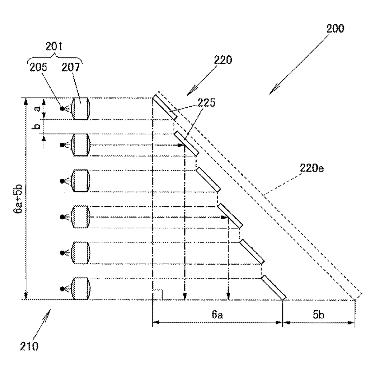
[0041]Referring to FIG. 3, which illustrates the structure of a light source system according to an embodiment of the present invention, the light source system includes a set of laser source 300, where each laser source 300 includes:

[0042]two laser groups 20a and 20b, where the laser group 20a includes two lasers 21a and 21b, and the laser group 20b includes two lasers 21c and 21d. The two laser groups are arranged in parallel, and the two light beams from the two lasers of the same laser group are in the same direction and parallel to each other;

[0043]two reflector groups 30a and 30b respectively corresponding to the two laser groups 20a and 20b, where the reflector group 30a includes two reflectors 31a and 31b respectively corresponding to the two lasers 21a and 21b, and the reflector group 30b includes two reflectors 31c and 31d respectively corresponding to the two lasers 21c and 21d; each reflector is disposed on the optical axis of its corresponding laser;

[0044]each reflector...


PUM


Abstract

Disclosed are a light source system and a laser light source (300). The laser light source includes two groups of laser groups (20a, 20b), wherein at least one group of laser groups includes at least two lasers (21a, 21b, 21c, 21d), and the light beams (L1) generated by the two groups of laser groups are in the same direction and parallel to each other. The first projections of the two groups of laser groups on the cross section of the light beams formed by the respective emergent light rays thereof are partially overlapped with the second projections in a first direction, which first direction is the connection direction of at least two laser centres of a group of laser groups. The laser light source has the effects of being able to effectively increase the light power density and at the same time reduce the volume of the light source.

Description

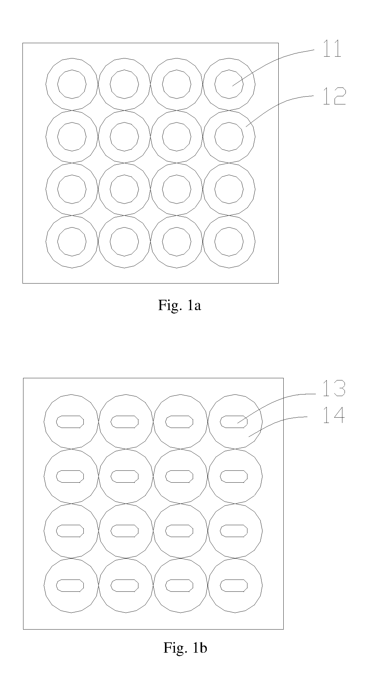
BACKGROUND OF THE INVENTIONField of the Invention[0001]This invention relates to optical technologies, and in particular, it relates to light source systems and laser light sources.Description of the Related Art[0002]In conventional technologies, the light power of a typical single semiconductor laser device is about a few hundred mW, or up to 1-2 W for higher powered ones. It is currently difficult to achieve output power of a few watts or over 10 W for single semiconductor laser devices.[0003]In some applications that require high power semiconductor lasers, such as projector, stage lighting system, etc., where the required light output is a few tens of watts, arrays of semiconductor lasers may be employed. Conventional semiconductor laser arrays simply arrange semiconductor lasers such as laser diodes in two-dimensional arrays, and use collimating lenses to collimate the light from the laser diodes.[0004]FIG. 1a shows a 4×4 laser diode array. Typical light distribution of a laser...

Claims


Application Information

Patent Timeline
Patent Type & Authority Applications(United States)
IPC IPC(8): H01S5/40F21Y113/00F21Y115/10F21Y115/30
CPCF21Y2115/10F21Y2113/00H01S5/4012H01S5/4087H01S5/4075F21Y2115/30F21V7/00G02B27/09G02B27/0916G02B27/10H01S5/00
Inventor HU, FEIYANG, JIAYI
Owner APPOTRONICS CORP LTD
Why Eureka
Try Eureka