
Thermally Controlled Variable-Flexibility Catheters and Methods of Manufacturing Same

a variable-flexibility, catheter technology, applied in the field of medical devices, can solve the problems of not being able to improve navigability, not being able to improve staying power, and not being able to move longitudinally without causing damage to the inflation site, so as to prevent kinking and maintain the circularity of the base catheter

Active Publication Date: 2018-10-11
SYN VARIFLEX LLC
View PDF7 Cites 28 Cited by
  • Summary
  • Abstract
  • Description
  • Claims
  • Application Information

AI Technical Summary

Benefits of technology

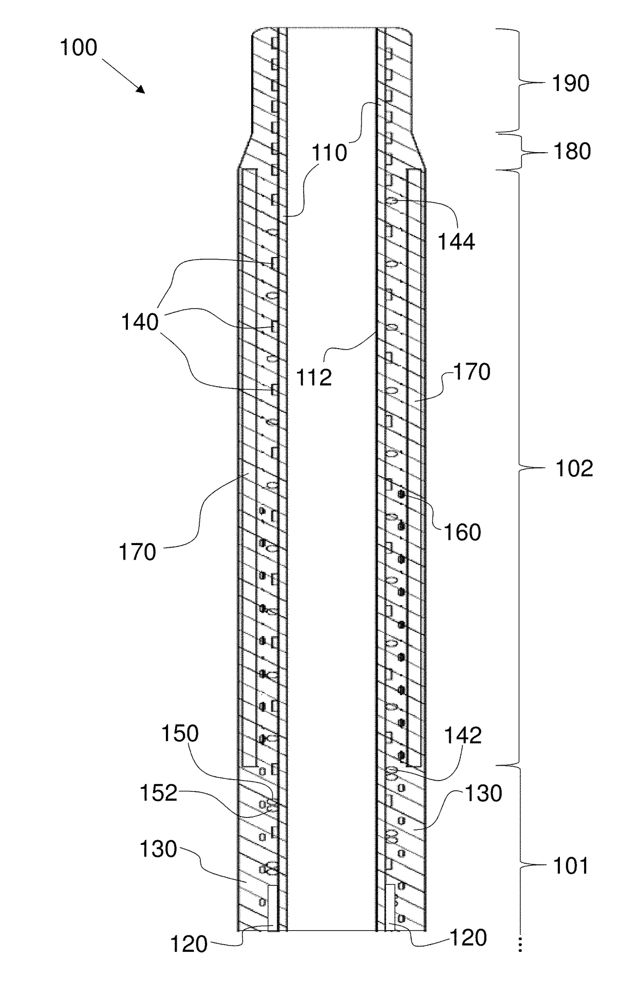
The patent describes a catheter that can be adjusted to be flexible or stiff as needed. This allows the catheter to be easily advanced through complex anatomies and provide better retention force. The catheter has a control system that regulates its stiffness using electrical heaters. This allows for precise control of the catheter's flexibility and ensures safe and reliable use in various medical procedures. The catheter is particularly useful in neurointerventional medicine. The technical effects of this invention include improved precision, safety, operating room time reduction, risk of accidents reduction, and procedure cost reduction.

Problems solved by technology

But, when so anchored, the catheter cannot move longitudinally without causing damage to the inflation site.
Balloon catheters are problematic due to their total occlusion of blood flow in a given vessel during use and for the stress they place on vessel walls, but they are also unusable if the procedure requires multiple sets of extensions into anatomy and securement therein for each step.
Accordingly, it is not possible currently to improve navigability without worsening staying power and equally not possible to improve staying power without worsening navigability.
A significant issue encountered with guide catheters is “back-out”, wherein pushing force applied to a catheter or implement within the guide catheter causes the guide catheter to move within the vasculature relative to its initial position.
Because of the strain energy stored in a deformed guide catheter, these “back-outs” can be very sudden and dramatic events.
Back-outs have adverse consequences with regard to patient safety and doctor success.
When a guide catheter dislodges, it often brings with it the additional catheters or implements being used for a procedure, compromising what is often a complex set of device positions and placements through the patient's vasculature.
This increases time in the operating room by necessitating re-catheterization of the patient.
If a “back-out” event occurs during a critical moment in a procedure, for example, with deployment of a flow diverter, back-out can damage a device costing $10,000 or more and potentially cause severe harm to the patient.
Another issue of relevance to catheters and catheter-based device users is ease of operation.
Devices constrained within the guide catheter's relatively stiff and smooth inner lumen are not able to buckle or push into compliant vessel walls.

Method used


Image

  • Thermally Controlled Variable-Flexibility Catheters and Methods of Manufacturing Same
  • Thermally Controlled Variable-Flexibility Catheters and Methods of Manufacturing Same
  • Thermally Controlled Variable-Flexibility Catheters and Methods of Manufacturing Same

Examples


Embodiment Construction

[0078]As required, detailed embodiments of the systems, apparatuses, and methods are disclosed herein; however, it is to be understood that the disclosed embodiments are merely exemplary of the systems, apparatuses, and methods, which can be embodied in various forms. Therefore, specific structural and functional details disclosed herein are not to be interpreted as limiting, but merely as a basis for the claims and as a representative basis for teaching one skilled in the art to variously employ the systems, apparatuses, and methods in virtually any appropriately detailed structure. Further, the terms and phrases used herein are not intended to be limiting; but rather, to provide an understandable description of the systems, apparatuses, and methods. While the specification concludes with claims defining the features of the systems, apparatuses, and methods that are regarded as novel, it is believed that the systems, apparatuses, and methods will be better understood from a conside...


PUM

PropertyMeasurementUnit
lengthsaaaaaaaaaa
outer diameteraaaaaaaaaa
diameteraaaaaaaaaa

Abstract

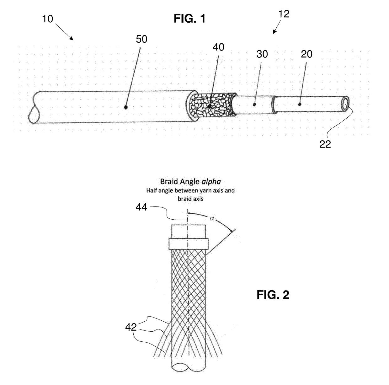
A catheter comprises a heater control supplying power, a handle, a base catheter with lumen and comprising a proximal section and a distal segment, and a variable stiffness element. The element comprises a heater connected to the heater control, coiled at least at the distal segment, and comprising a shaft portion of a first metallic conductive material and a heater portion of a second metallic conductive material. A jacket is disposed about the heater portion. A variable flex sub-assembly between the catheter and jacket comprises a non-conducting braid and a binding material. Without power, the binding material is stiffened. Responsive to heating of the binding material, the binding material softens to increase flexibility of the variable flex sub-assembly at least at the distal segment. Responsive to removing power, the binding material cools and stiffens to decrease flexibility of the variable flex sub-assembly at least at the distal segment.

Description

CROSS-REFERENCE TO RELATED APPLICATIONS[0001]This application claims the priority, under 35 U.S.C. § 119, of copending U.S. Provisional Patent Application No. 62 / 483,736, filed Apr. 10, 2017, and U.S. Provisional Patent Application No. 62 / 644,797, filed Mar. 19, 2018; the prior applications are herewith incorporated by reference herein in their entirety.STATEMENT REGARDING FEDERALLY SPONSORED RESEARCH OR DEVELOPMENT[0002]Not ApplicableFIELD OF THE INVENTION[0003]The present systems, apparatuses, and methods lie in the field of medical catheters. The present disclosure relates to thermally controlled, variable-flexibility catheters and methods of manufacturing such catheters.BACKGROUND OF THE INVENTION[0004]Catheters have many uses in modern medicine. One reason for their importance is their ability to guide and support additional instruments during a procedure at an anatomic location. In the procedure, a guide catheter is inserted between an entry site and advanced as far as is safe...

Claims


Application Information

Patent Timeline
Patent Type & Authority Applications(United States)
IPC IPC(8): A61M25/00A61M25/01
CPCA61M25/0054A61M25/0009A61M25/005A61M25/0133A61M25/0045A61M2025/0064B29K2995/0082A61M25/0662A61B1/00078A61M25/0043
Inventor PALMER, MATTHEW A.BALES, JR., THOMAS O.BOND, TYLERPETERSEN, ERICDEVILLE, DEREK DEEBALES, WILLIAM T.WEGER, MATTHEW
Owner SYN VARIFLEX LLC
Learn More