Communication connector and communication connector with cable
a technology of communication connector and communication connector, which is applied in the direction of two-part coupling devices, line/current collector details, and coupling device connection, etc., can solve the problems reducing communication quality, and reducing communication quality, so as to suppress the effect of reducing communication quality
- Summary
- Abstract
- Description
- Claims
- Application Information
AI Technical Summary
Benefits of technology
Problems solved by technology
Method used
Image
Examples
first embodiment
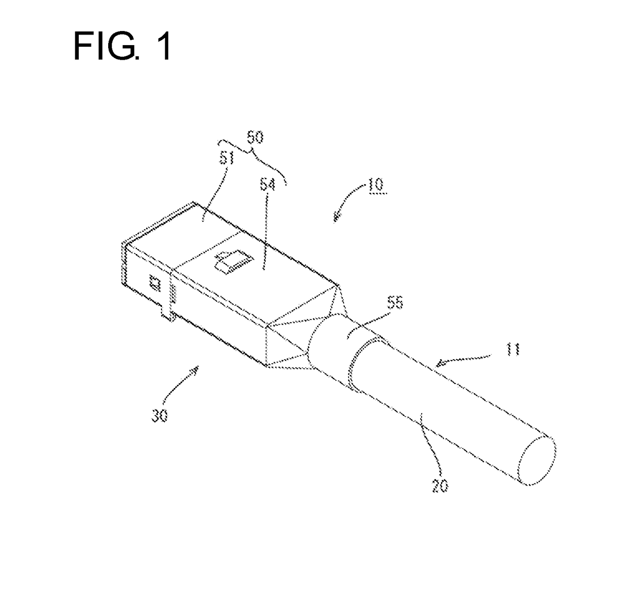
[0037]A first embodiment is described with reference to FIGS. 1 to 11.
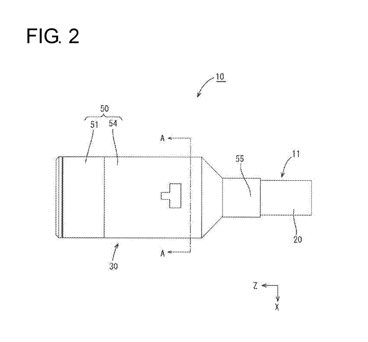
[0038]A communication connector with cable 10 is mounted in a vehicle, such as an electric or hybrid vehicle, and is disposed in a wired communication path, such as between an in-vehicle electrical device (navigation system, ETC, monitor, etc.) in the vehicle and an external device (camera, etc.) or between the in-vehicle electrical devices. In the following description, a left side (Z direction) and a right side of FIG. 2 are referred to as a front and rear concerning a front-rear direction, and a vertical direction and a lateral direction are based on directions of FIG. 3 (X direction extends rightward and Y direction extends up).
[0039](Communication Connector with Cable 10)
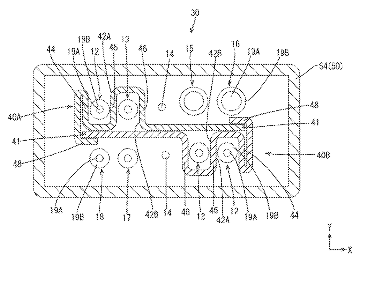
[0040]The communication connector with cable 10 of this embodiment includes a cable 11 and a communication connector 30 provided on an end part of the cable 11, as shown in FIGS. 2 and 3. The cable 11 is capable of high-speed communication at...
second embodiment
[0062]A second embodiment is described with reference to FIGS. 12 to 16. In the second embodiment, alignment members 61A, 61B are not provided with the locking portions 48 of the first embodiment and the alignment members 61A, 61B and wires 12 to 18 are collectively wound with tape. In the following description, the same components as in the first embodiment are denoted by the same reference signs and not described.
[0063]A communication connector 60 includes terminals 31, a housing 35, alignment members 61A, 61B and a shield case 50. The alignment members 61A, 61B are formed by omitting the locking portions 48 from the alignment members 40A, 40B of the first embodiment.
[0064]A tape 62 is formed with a thin metal layer over the entire surface and an adhesive layer formed of an adhesive may be laminated on the metal layer. Further, a resin layer may be overlaid to enhance strength or an adhesive layer may be formed between the metal layer and a resin layer both having flexibility. A l...
third embodiment
[0067]A third embodiment is described with reference to FIGS. 17 to 20. In a communication connector 70 of the third embodiment, each alignment member 71A, 71B is provided with three insertion grooves 73A to 73C. In the following description, the same components as in the above embodiments are denoted by the same reference signs and not described.
[0068]The alignment members 71A, 71B have the same shape, are disposed to be connected behind an extending portion 38 and formed by stamping and bending a metal plate material, such as aluminum, aluminum alloy, copper or copper alloy. Each alignment member 71A, 71B includes a flat plate 72 extending in a lateral direction, the insertion grooves 73A to 73C into which wires 12 to 14 are inserted, and a locking portion 79 to be locked to the other alignment member 71A, 71B.
[0069]The insertion grooves 73A to 730 are disposed in opposite orientations via common partition walls 76, 77 and the wires 12 to 14 can be inserted from opposite vertical ...
PUM
 Abstract
Description
Claims
Application Information
 - R&D
- Intellectual Property
- Life Sciences
- Materials
- Tech Scout
- Unparalleled Data Quality
- Higher Quality Content
- 60% Fewer Hallucinations
Browse by: Latest US Patents, China's latest patents, Technical Efficacy Thesaurus, Application Domain, Technology Topic, Popular Technical Reports.
© 2025 PatSnap. All rights reserved.Legal|Privacy policy|Modern Slavery Act Transparency Statement|Sitemap|About US| Contact US: help@patsnap.com


