
Metal laminate material and production method therefor

a metal laminate material and production method technology, applied in the field of metal laminate materials and a production method therefor, can solve the problems of poor molding processability, poor radiation performance of carbon sheets, poor molding processability of metal laminate materials of stainless steel and aluminum, produced by cold rolling, etc., to achieve excellent radiation performance, light weight, and good heat dissipation

Active Publication Date: 2018-10-04
TOYO KOHAN CO LTD
View PDF2 Cites 5 Cited by
  • Summary
  • Abstract
  • Description
  • Claims
  • Application Information

AI Technical Summary

Benefits of technology

The present invention provides a metal laminate material that has good strength, can be easily molded, performs well in radiation, and is lightweight.

Problems solved by technology

Although high strength aluminum materials are lightweight and excellent in radiation performance, they have poor molding processability.
Meanwhile, although a laminate material of a stainless steel and a carbon sheet is excellent in molding processability, the carbon sheets are very expensive and inferior to aluminum materials in terms of radiation performance.
A metal laminate material of stainless steel and aluminum, which is produced by cold rolling, has poor molding processability because stainless steel and aluminum become hardened as a result of work-hardening.
However, since the recrystallization temperature of stainless steel is higher than the melting point of aluminum, heat treatment in a temperature range that allows recrystallization of stainless steel would cause aluminum to melt.
For such reason, it is impossible to recrystallize both work-hardened stainless steel and aluminum in the metal laminate material of stainless steel and aluminum, which is produced by cold rolling, making it difficult to obtain a material having sufficient molding processability.
However, in a case in which thickness of the metal laminate material is as small as not more than 500 μm, it results in poor molding processability.

Method used


Image

  • Metal laminate material and production method therefor
  • Metal laminate material and production method therefor
  • Metal laminate material and production method therefor

Examples


examples

[0068]The present invention is described in detail with reference to the Examples and Comparative Examples below. However, the present invention is not limited to these Examples.

example 6

[0088]In order to presume a preferable reduction rate for bonding a stainless steel foil and an aluminum foil or a two-layer material by pressure-bonding, the metal laminate material obtained in Example 3-2 was rolled at different reduction rates, and the dome height in Erichsen cupping test was determined for each of the rolled metal laminate materials. Table 6 lists the results. The metal laminate material in Example 3-2 corresponds to a reduction rate of 0% in Table 6.

TABLE 6ReductionSurfaceTensileDomerateThicknessHardnessStrength TSElongationHeight(%)(μm)Hv(MPa)(%)(mm)0388180.7413.5518.610352240.5462.3496.520311300.2522.2314.530275336.6——3.640233365.4——3.050194371.6612.0113.0

[0089]As shown in Table 6, when the reduction rate was not less than 20%, the dome height in Erichsen cupping test for each corresponding metal laminate material was less than 4.6 mm, resulting in insufficient molding processability of the metal laminate material. Meanwhile, when the reduction rate was not m...

example 7

[0090]The average crystal grain size in the stainless steel layer was determined for the metal laminate materials in Examples 1-1, 1-2, and 2-2 as described below. First, each of samples of the metal laminate materials was immersed in about one-third dilution of aqua regia serving as a corrosive liquid for 10 to 15 minutes, thereby etching the stainless steel layer. Subsequently, a cross-section of the etched stainless steel layer of each sample was observed from TD in a sample coordinate system using SEM (electric-field-emission electron scanning microscope SU8020 manufactured by Hitachi High-Technologies Corporation). The average crystal grain size was calculated based on the above definition from each observation image. In addition, the average crystal grain size was determined also for a stainless steel foil 1 and a stainless steel foil 2 before bonding for reference. Table 7 lists the measurement results. FIGS. 9A to 9C are SEM observation images of the stainless steel foil 1, ...


PUM

PropertyMeasurementUnit
elongationaaaaaaaaaa
thicknessaaaaaaaaaa
lengthaaaaaaaaaa

Abstract

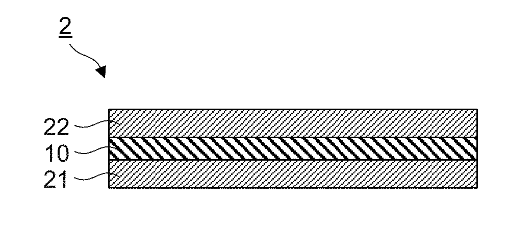
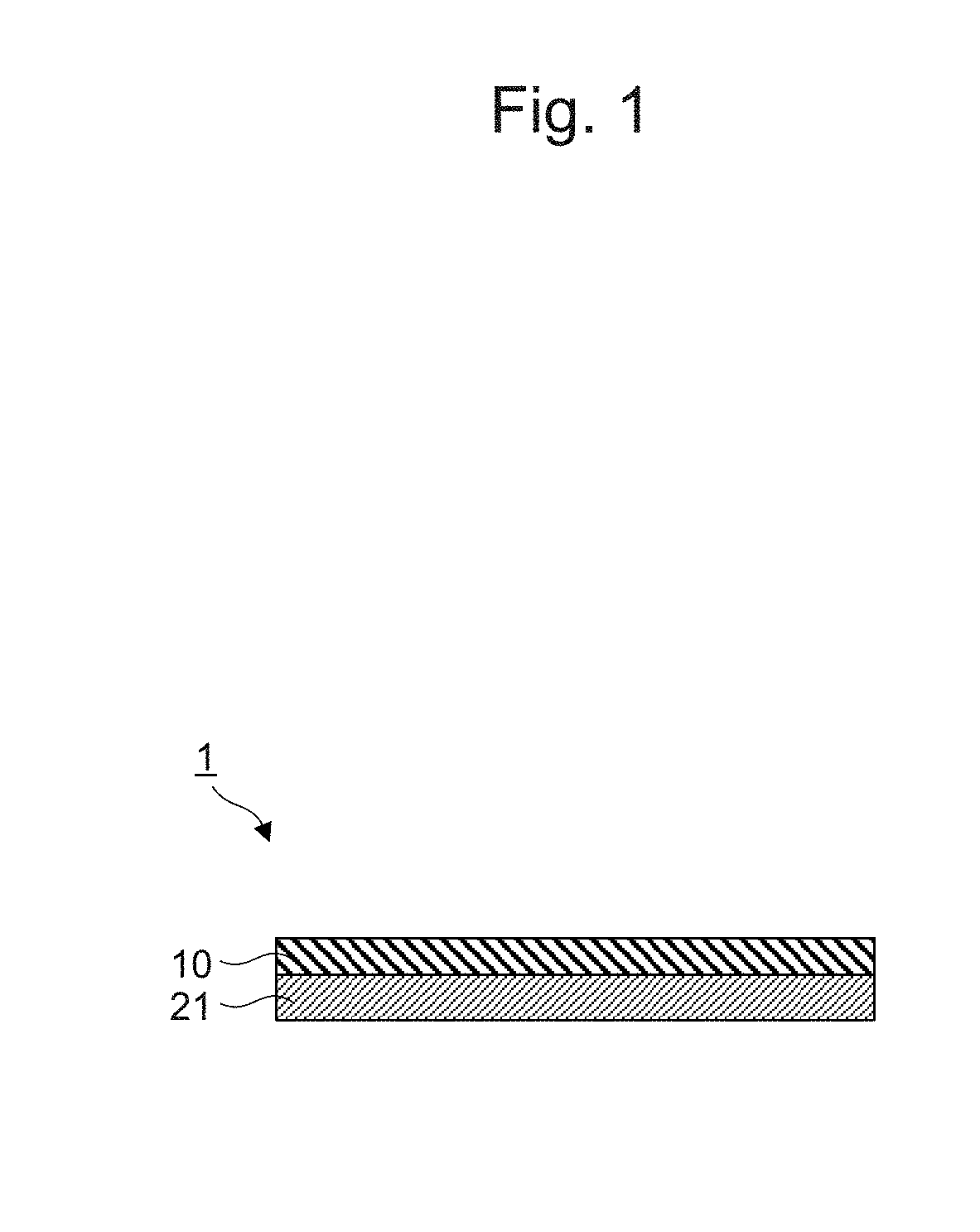
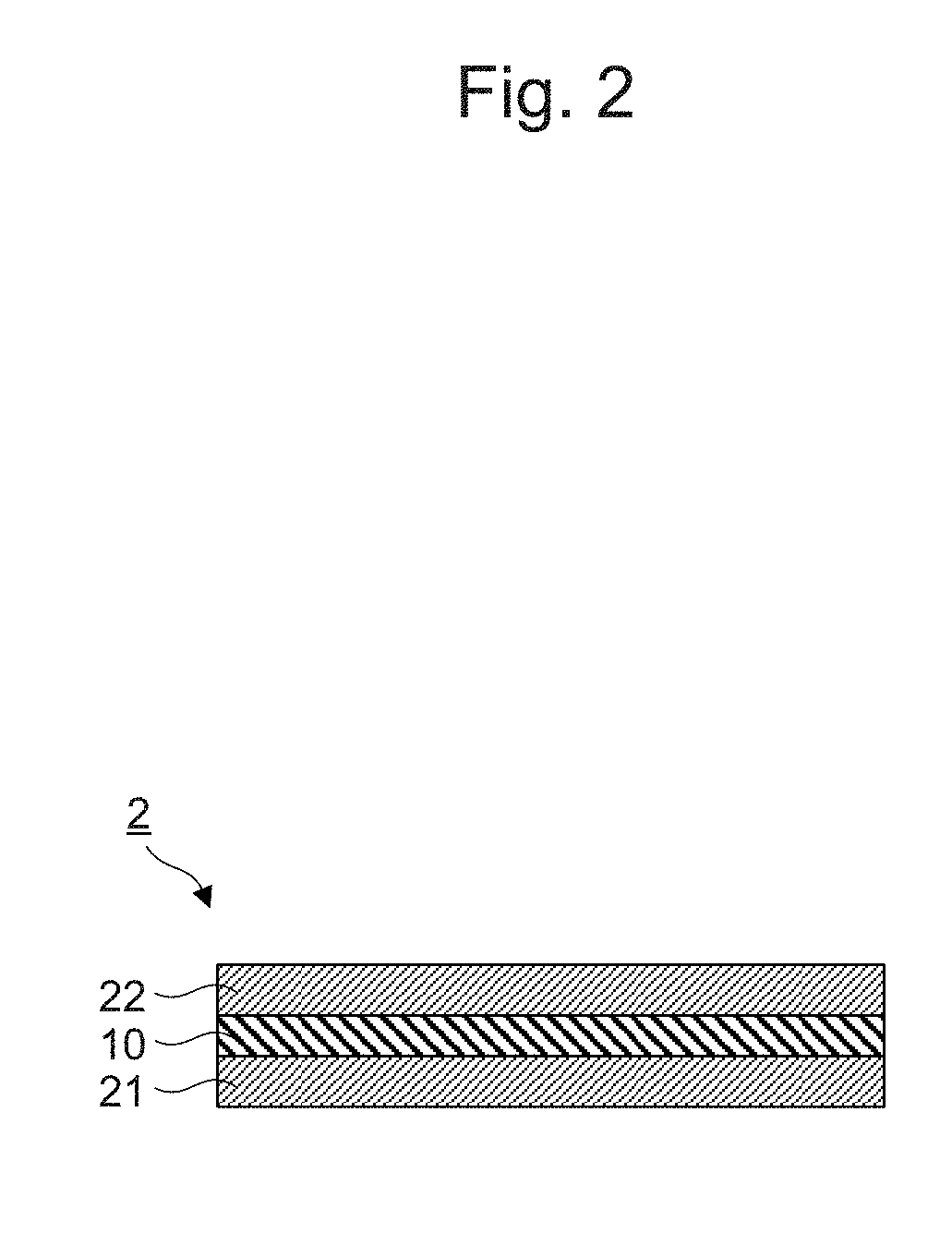
It is an objective of the present invention to provide a metal laminate material, which has sufficient strength as well as molding processability, lightweight properties, and radiation performance, which is a metal laminate material that has a two-layer structure of a stainless steel layer and an aluminum layer or a three-layer structure of a 1st stainless steel layer, an aluminum layer, and a 2nd stainless steel layer, wherein tensile strength TS is 200≤TS≤550 (MPa), elongation EL is not less than 15%, and a surface hardness Hv of the stainless steel layer is not more than 300 for the metal laminate material.

Description

TECHNICAL FIELD[0001]The present invention relates to a metal laminate material and a production method therefor.BACKGROUND ART[0002]Metal materials are used in various fields. For example, metal materials are used for heat radiating members for electronic devices such as mobile electronic devices, etc. Metal materials used for such members are required to have lightweight properties, high strength, high radiation performance, and molding processability. As such metal materials, laminate materials, in which a high strength aluminum material or a stainless steel and a carbon sheet are laminated, are widely used at present.[0003]Although high strength aluminum materials are lightweight and excellent in radiation performance, they have poor molding processability. Meanwhile, although a laminate material of a stainless steel and a carbon sheet is excellent in molding processability, the carbon sheets are very expensive and inferior to aluminum materials in terms of radiation performance...

Claims


Application Information

Patent Timeline
Patent Type & Authority Applications(United States)
IPC IPC(8): B23K20/04B32B15/01C21D6/00C21D9/46B21B1/22C22C38/06
CPCB23K20/04B32B15/01C21D6/00C21D9/46B21B1/22C22C38/06B32B15/012B23K2103/20C21D2251/02C22C38/40C22C38/44Y10T428/12757B32B2250/02B32B2250/03B32B2250/40B32B2307/302B32B2307/538B32B2307/54B32B2309/105C23F4/00
Inventor NANBU, KOUJIKUROKAWA, TEPPEIKOSHIRO, TAKASHIOKAYAMA, HIRONAO
Owner TOYO KOHAN CO LTD
Learn More