


Quick Research
Generate reliable direction feasibility study reports for your R&D in just a few steps.

Technical Q&A
Discover and master advanced knowledge NOW. Basics, ideas, possibilities, all at once.

Find Solutions
As an expert in R&D theories, this can generate solutions to your technical problems instantly.

Evaluate Feasibility
Analyze your overall solution with one click, know your potential R&D risks in advance.

Monitor Landscape
Get weekly tech updates, stay abreast of the latest tech innovations and key insights.
Mouse device
- Summary
- Abstract
- Description
- Claims
- Application Information
AI Technical Summary
Benefits of technology
Problems solved by technology
Method used
Image

Examples
first embodiment
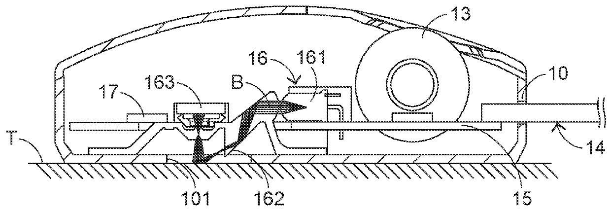
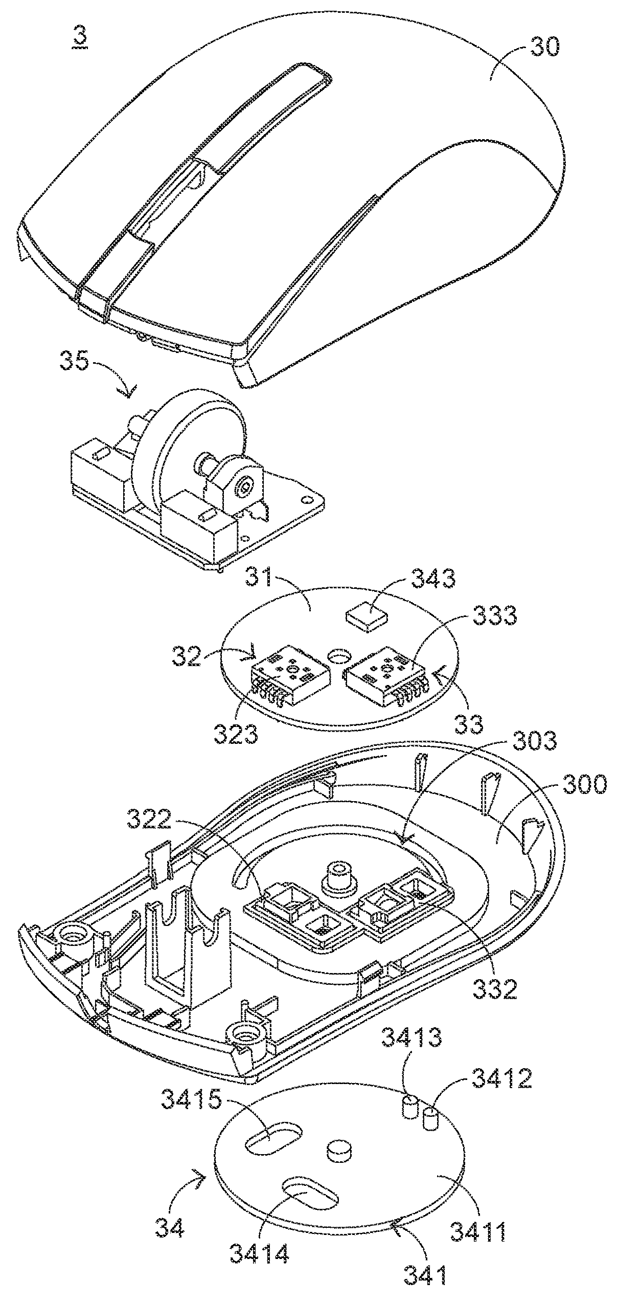
[0033]The structures of the first sensing module 32 and the second sensing module 33 will be described with reference to FIGS. 3, 4 and 6. FIG. 6 is a schematic cross-sectional view illustrating a portion of the mouse device according to the present invention. The first sensing module 32 comprises a first light-emitting element (not shown), a first optical lens 322 and a first optical sensor 323. The second sensing module 33 comprises a second light-emitting element 331, a second optical lens 332 and a second optical sensor 333. In FIG. 6, the detailed structure of the second sensing module 33 is shown. That is, the second sensing module 33 will be taken as an example for illustration. The second light-emitting element 331 is disposed on the circuit board 31 and electrically connected with the controlling unit 343. Moreover, the second light-emitting element 331 emits a light beam B. The second optical lens 332 is disposed on the bottom part 300 of the mouse casing 30. The light bea...
second embodiment
[0042]Please refer to FIGS. 10, 11 and 13. FIG. 13 is a schematic bottom view illustrating the mouse device of the second embodiment in a second status. When the mouse device 4 is used to operate the computer game and it is necessary to increase the moving resolution of the mouse device 4, the user may move the switching plate 441 in a second direction D2. Consequently, the plate body 4411 within the receiving recess 404 is moved relative to the mouse casing 40 in the second direction D2. In addition, the second protrusion post 4413 is moved from the nearby position of the first end 4031 of the track 403 to a second end 4032 of the track 403, and the first protrusion post 4412 is moved from the first end 4031 of the track 403 to the nearby position of the second end 4032 of the track 403. Consequently, the second sensing module 43 is exposed to the outside. While the first protrusion post 4412 and the second protrusion post 4413 are moved, the first protrusion post 4412 and the seco...
PUM
 Abstract
Description
Claims
Application Information
 - R&D Engineer
- R&D Manager
- IP Professional
- Industry Leading Data Capabilities
- Powerful AI technology
- Patent DNA Extraction
Browse by: Latest US Patents, China's latest patents, Technical Efficacy Thesaurus, Application Domain, Technology Topic, Popular Technical Reports.
© 2024 PatSnap. All rights reserved.Legal|Privacy policy|Modern Slavery Act Transparency Statement|Sitemap|About US| Contact US: help@patsnap.com