Method for Assembling Tubular Joining Sleeve and a Conduit Lining Tube by Laser Welding

a technology of laser welding and tubular joining sleeve, which is applied in the direction of manufacturing tools, other domestic objects, mechanical equipment, etc., can solve the problems of heater wire leading to the sleeve melting over its entire thickness, and it is not possible to go below a thickness of preferably 3 mm, so as to reduce the energy required for laser welding and reduce the constraint. , the effect of easy quality inspection

Active Publication Date: 2018-09-27
SAIPEM SA
View PDF0 Cites 3 Cited by
  • Summary
  • Abstract
  • Description
  • Claims
  • Application Information

AI Technical Summary

Benefits of technology

[0036]Another advantage of the present invention compared with electrofusion welding is to eliminate the constraint of using heater wires and of positioning electrical connectors for the heater wires in one of the tubes, in particular in a said tubular junction sleeve.
[0037]Another advantage of the present invention is that the energy required for the laser is relatively smaller, e.g. of the order of 50 watts (W) to 100 W, since laser welding can be performed validly in practice over a thickness of 1 mm to 2 mm, both for the transparent portion and for the absorbent portion. The weld penetrates less deeply into the absorbent portion when it is more absorbent and thus more filled with opacifying agent, and in particular with carbon black.
[0038]Another advantage of such assembly by laser welding is that it makes it easier to inspect the quality of the welding by analyzing the absorption of the welded zone. To do this, it suffices to send a second laser beam for inspection purposes under the same conditions and with the same device onto the weld zone and to analyze the power absorbed by analysis using photocells that are sensitive to the second beam as returned by reflection on the non-welded zones, as explained below.
[0039]All of these advantages of the laser welding of the present invention make it possible to maximize reliability and also to optimize working time when making the weld and when using it for assembling together tubes in accordance with the present invention.
[0040]Such an implementation is also advantageous in that it makes it possible to use a liner of small thickness than is possible with electrofusion welding.
[0041]For laser welding, unlike electrofusion welding, a smaller thickness leads to greater effectiveness of the welding since absorption is less.

Problems solved by technology

A problem that then arises is to provide corrosion protection for the non-lined zone extending between the end of the liner of pipe element N and the end of the liner of the following pipe element N+1.
When the pipe is a water injection pipe, in the event of water penetrating between the sleeve and the pipe, such direct contact could lead specifically to electrochemical corrosion phenomena of the steel pipe and of the weld, insofar as said mechanical connection between the sleeve and the liner is not necessarily sealed.
In particular, because the sleeve needs to have the heater wire pass therethrough so as to reach its outer surface, the heater wire leads to the sleeve melting over its entire thickness if the sleeve is not sufficiently thick.
Nevertheless, given the constraints acting on the internal liner while it is being put into place, where a thermoplastic liner tube is inserted by traction and striction through a die inside a steel unit pipe element having a length of about 50 m, it is not possible to go below a thickness of preferably 3 mm, since the tube might then be pressed poorly against the steel pipe.

Method used


Image

  • Method for Assembling Tubular Joining Sleeve and a Conduit Lining Tube by Laser Welding
  • Method for Assembling Tubular Joining Sleeve and a Conduit Lining Tube by Laser Welding
  • Method for Assembling Tubular Joining Sleeve and a Conduit Lining Tube by Laser Welding

Examples


Embodiment Construction

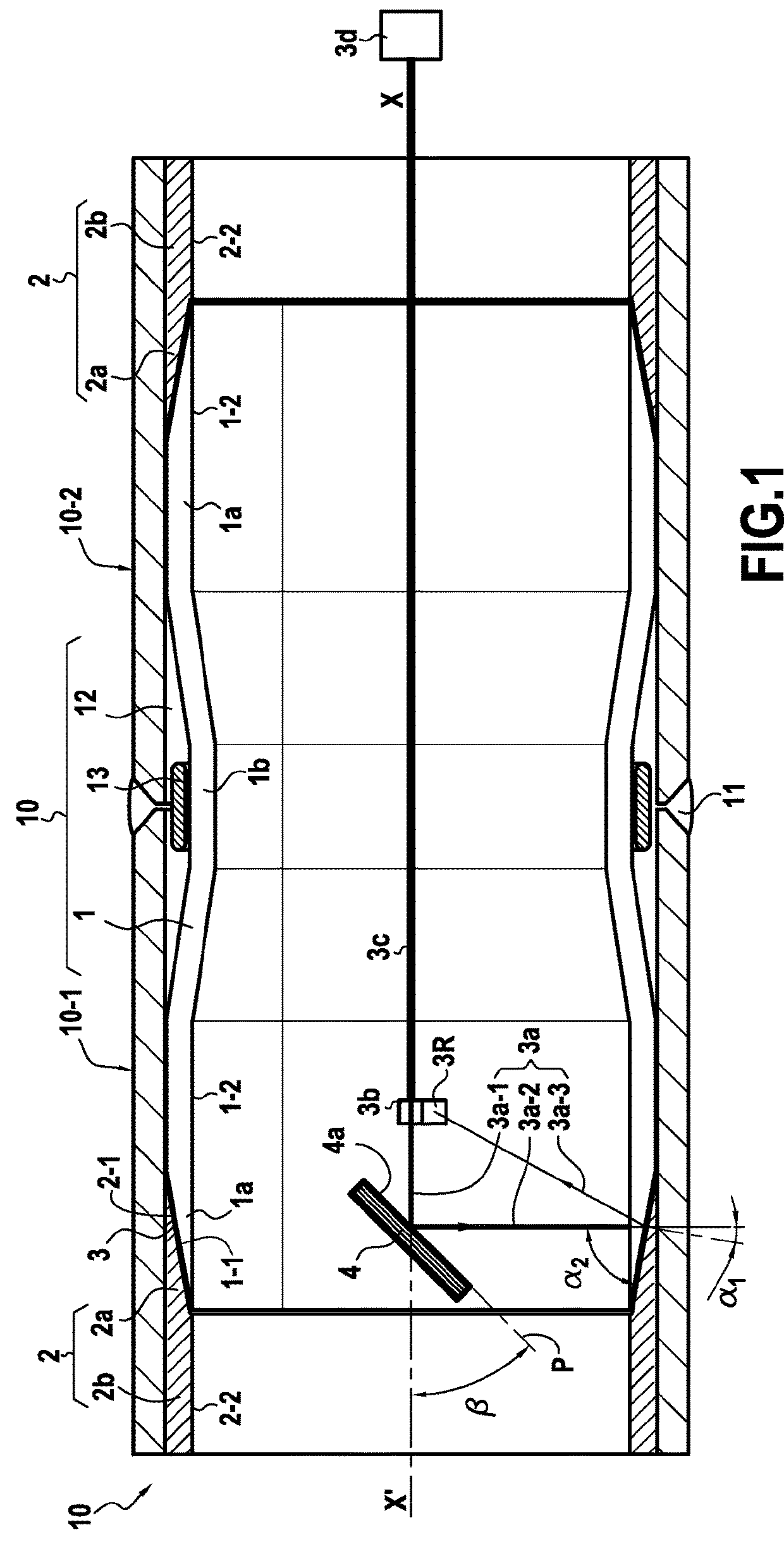
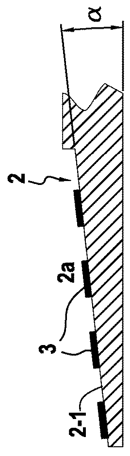
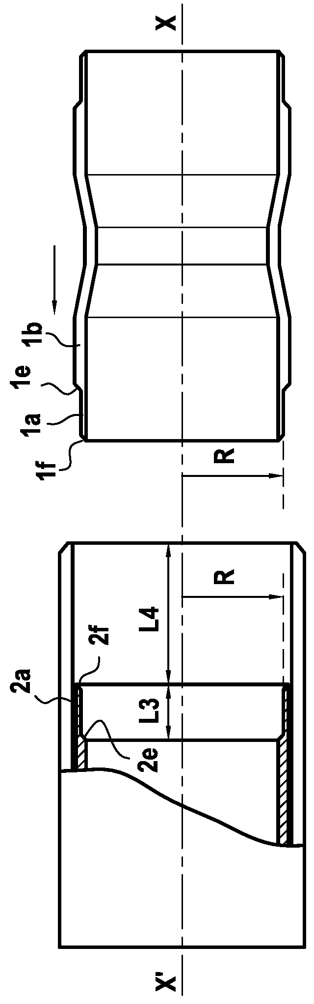
[0179]FIG. 1A shows a pipe 10 of the invention having at least two pipe elements 101, 102 with internal liners 2 made of polyethylene or polypropylene, which elements are assembled together end-to-end, and the ends of two pipe elements are welded together at 11. Each pipe element has an internal liner 2 made of thermoplastic material having an axis XX′ coinciding substantially with the axis of the pipe elements 101, 102, and presenting at each end a conical terminal portion 2a having a half-angle at the apex a lying in the range 5° to 15°, and in particular about 10°, and of thickness that is smaller than the thickness of the main portion 2b of said liner, defining a concave shape with a frustoconical inner surface of revolution having a contact surface 2-1 of inside diameter that is greater than the inside diameter of the main portion 2b of said liner and that terminates at a certain distance L from each end of said pipe elements. The outer surface of each said terminal portion 2a ...


PUM

PropertyMeasurementUnit
thicknessaaaaaaaaaa
angleaaaaaaaaaa
angleaaaaaaaaaa

Abstract

The present invention relates to a method and to a device for assembling together two tubes (1, 2) comprising a tubular junction sleeve and an internal pipe liner tube made of thermoplastic materials by laser welding two contact surfaces of revolution (1-1, 2-1) pressed one against the other at the ends of the tubular sleeve of said liner tube overlapping coaxially.

Description

PRIORITY CLAIM[0001]This is a U.S. national stage of application No. PCT / FR2016 / 052392, filed on Sep. 21, 2016. Priority is claimed on French Application No. FR 1558960, filed on Sep. 23, 2015, the content of which is incorporated here by reference.BACKGROUND OF THE INVENTION1. Field of the Invention[0002]The present invention relates to a method of using laser welding to assemble together tubes made of thermoplastic materials. More particularly, the present invention applies to assembling together at least two tubes arranged end-to-end or overlapping coaxially at least in part.[0003]Still more particularly, the present invention relates to assembling together: a) a tubular junction sleeve inserted inside a pipe, in particular an undersea pipe, at a junction between two steel pipe elements that are, or that are to be, metal butt-welded together; and b) an internal liner tube applied as internal covering for said pipe elements.[0004]More particularly, the present invention relates to...

Claims


Application Information

Patent Timeline
Patent Type & Authority Applications(United States)
IPC IPC(8): B29C65/16B29C65/82B29C65/00F16L47/02
CPCB29C65/1635B29C65/1677B29C65/8253B29C66/1122B29C66/1142B29C66/14B29C66/5221B29C66/612B29C66/634B29C66/73921B29C66/81267B29C66/81455F16L47/02B29K2507/04B29K2995/0027B29L2023/22B29C65/1654B29C65/1687B29C65/8292B29C66/1222B29C66/1224B29C66/1226B29C66/12821B29C66/12861B29C66/53241B29C66/652B29C66/71B29C66/72321B29C66/836B29C66/24B29C66/0016B29C66/5229B29C66/5344B29K2027/16B29K2023/12B29K2023/065B23K26/106B29D23/003
Inventor PIONETTI, FRANÇOIS-RÉGISLIROLA, FRANÇOISMAJDOUB, TAOUFIK
Owner SAIPEM SA
Why Eureka
Try Eureka