
Lithium Battery Containing Cathode Material and Electrolyte Additives for High Voltage Application

a lithium ion battery and additive technology, applied in batteries, cell components, electrochemical generators, etc., can solve the problems of inability to cycle in a stable manner at high voltage, limited cathode system, and fast capacity fading

Active Publication Date: 2018-09-06
UMICORE AG & CO KG +1
View PDF2 Cites 3 Cited by
  • Summary
  • Abstract
  • Description
  • Claims
  • Application Information

AI Technical Summary

Benefits of technology

The invention provides a lithium secondary cell with improved performance. The cell has a cathode with a powderous doped LiCoO2 active material, a graphite anode, and an electrolyte containing a carbonate-based solvent, a lithium salt, and additives. The active material is doped with at least one of Mn, Mg, and Ti, and the ratio of the Mn in the surface layer to the Mn in the core of the material is at least 7%. The cell also has a high discharge capacity at 45°C and a low temperature discharge capacity at 3V. The electrolyte may contain 0.5-3 wt% succinonitrile and 0.5-2 wt% lithium bis(oxalato)borate. The active material may have a layered crystal structure or a plurality of islands densely sintered to the core, and the surface layer may consist of Ni and at least 5 mole % of Mn or Mg. The molar content of M2 in the material is at least 4% or 6%. The active material may have the general composition LixCo1−a′−b'M3a'M4b'O2-d' or LixCo1−a'−b'M3a'M4b'O2-d', with M4 being Al or Al and either one or more metals from the group consisting of Mg, Ca, Ti, or Zr.

Problems solved by technology

However, the improvement is limited by the cathode system.
State-of-the-art LiCoO2-based cathode materials generally have a high gravimetric density, but are not cycling in a stable manner at high voltage.
However, charge-discharge cycling of LiCoO2 under such high upper cutoff voltage (≥4.35V) results in fast capacity fading, which is considered to be due to the structural instability of de-intercalated LiCoO2, and to side reactions between the unstable surface of LiCoO2 and the electrolyte.
Thus, the oxidizing surface dramatically increases unwanted side reactions with the electrolyte being a reducing agent.
All these effects cause a continuous deterioration of the electrochemical performance of the battery: a loss of capacity and a strong increase of internal resistance (also known as polarization) is observed.
Thus, inherently, LiCoO2 has a severe storage issue, which gets worse when the cut-off voltage is increased.
However, this electrolyte additive causes undesired side-effects.
However, considering that cells are used at varying temperatures, like it is the case when cells are charged and stored at high temperature and then cycled at normal temperature, the impedance build-up in the period of high temperature can bring an inevitable negative effect on cycling at normal temperature.

Method used


Image

  • Lithium Battery Containing Cathode Material and Electrolyte Additives for High Voltage Application
  • Lithium Battery Containing Cathode Material and Electrolyte Additives for High Voltage Application
  • Lithium Battery Containing Cathode Material and Electrolyte Additives for High Voltage Application

Examples


example 1

Counter Example 1

[0087]This example presents Al-, Ti- and Mg-doped LiCoO2-based powder. This material is manufactured following the same steps as the preparation of Ex1 except that in the second step the molar content of MgO, Al2O3 and TiO2 powders vs. total Co is changed to 0.18% / 0.348% / 0.283% (Mg / Al / Ti). The prepared powder is named CEx1. It is applied as cathode material and tested following the description of “Coin cell test” and “Floating test”.

Discussion of Example 1, Example 2 and Counter Example 1

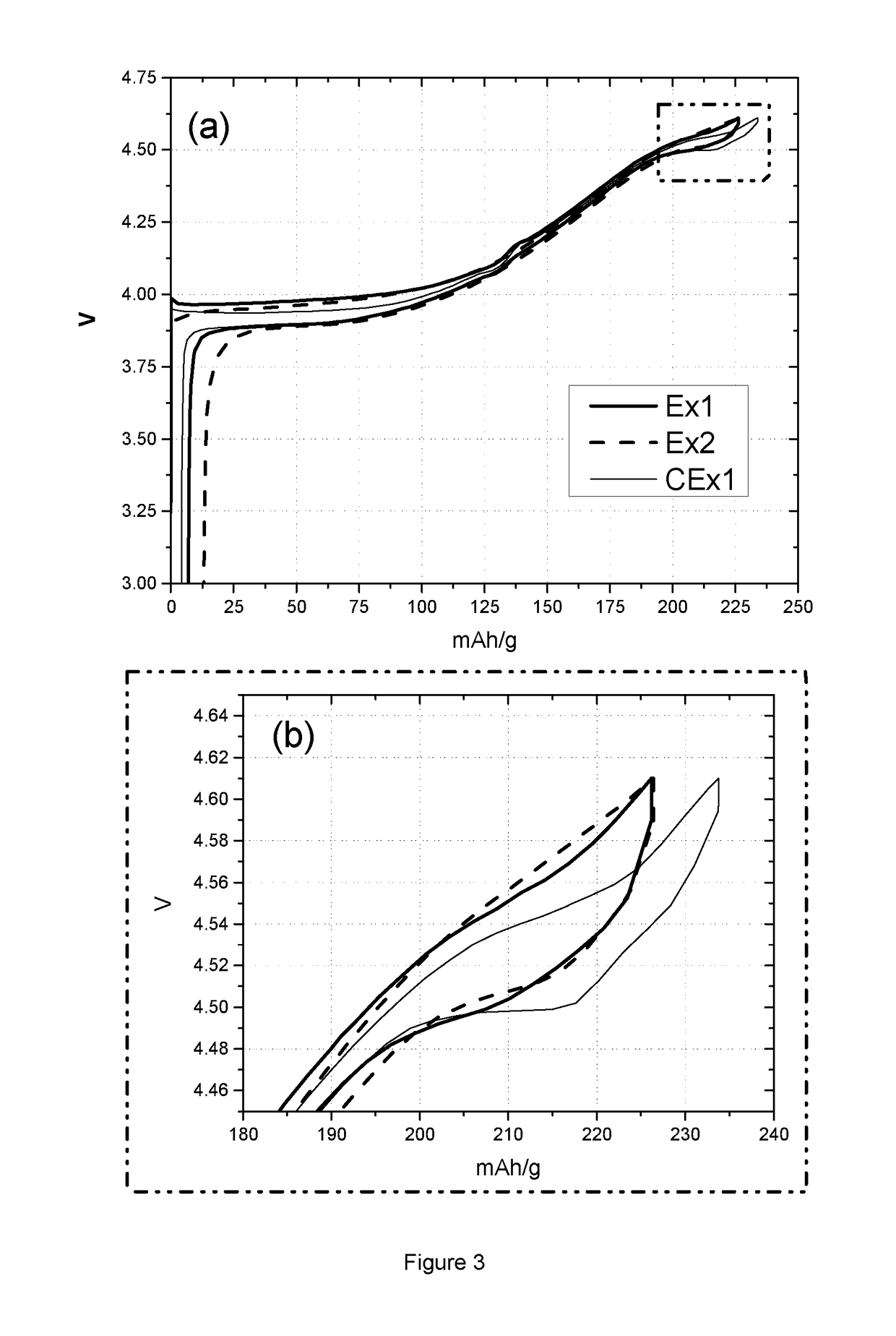
[0088]Table 3 lists the coin cell and floating test results of sample Ex1, Ex2 and CEx1. Coin cell tests provide charge and discharge capacity (CQ1 and DQ1) in the first cycle, and capacity lost after 98 times of cycling at 0.2C in the voltage range of 4.4 to 4.61V. The charge capacities of sample Ex1 and Ex2 are smaller than the value of sample CEx1, as is the case also for discharge capacity. This phenomenon can also be observed from FIG. 3, where graph (a) shows the 1st cycle vol...

example 2

Counter Electrolyte with Additives of SN

[0096]This example presents a rechargeable lithium ion battery prepared through the same procedure as Cell 1, except that the electrolyte additives (c) only comprise 2 wt % of succinonitrile (SN). The prepared 650 mAh pouch-type battery is named Cell 2.

Counter Example 3: Electrolyte with Additives of SN and LiBF4

[0097]This example presents a rechargeable lithium ion battery prepared through the same procedure as Cell 1, except that the electrolyte additives (c) only comprise 2 wt % of succinonitrile (SN) and 0.2 wt % of lithium tetrafluoroborate (LiBF4). The prepared 650 mAh pouch-type battery is named Cell 3.

example 4

Counter Electrolyte with Additives of SN and PRS

[0098]This example presents a rechargeable lithium ion battery prepared through the same procedure as Cell 1, except that the electrolyte additives (c) only comprise 2 wt % of succinonitrile (SN) and 0.5 wt % of propene sultone (PRS). The prepared 650 mAh pouch-type battery is named Cell 4.

Counter Example 5: Electrolyte with Additives of SN and VC

[0099]This example presents a rechargeable lithium ion battery prepared through the same procedure as Cell 1, except that the electrolyte additives (c) only comprise 2 wt % of succinonitrile (SN) and the solvent has been modified by adding 1 wt % of vinylene carbonate (VC). The prepared 650 mAh pouch-type battery is named Cell 5.


PUM


Abstract

A lithium secondary cell having an operating voltage ≥4.35 sV, comprising a cathode comprising a doped L1CoO2 active material, an anode comprising graphite, and an electrolyte comprising a carbonate-based solvent, a lithium salt and both a succinonitrile (SN) and a lithium bis(oxalato)borate (LiBOB) additive wherein during the discharge at 45° C. from a state of charge (SOC) of 100% at 4.5V to a SOC of 0 at 3V at a C / 10 rate the difference of the SOC at 4.42V and 4.35V is at least 7% but less than 14%, and wherein the active material is doped by at least 0.5 mole % of either one or more of Mn, Mg and Ti.

Description

TECHNICAL FIELD AND BACKGROUND[0001]This invention relates to secondary lithium ion batteries, containing positive electrode material and electrolyte additives, which are useful for a high voltage application. More particularly, the positive electrode comprises a lithium cobalt oxide compound.[0002]In recent decades, rechargeable lithium-ion batteries have been widely used in a variety of portable electronics applications, such as cellular phones, laptop computers, digital cameras and video cameras. Commercial lithium ion batteries employ lithium cobalt oxide as cathode material and graphite as anode material. With the development of customer electronics, there is a surge towards lithium cobalt oxide based secondary lithium ion batteries with higher energy density. In last years, initial efforts have been made for the optimization of cell design, including packing technology, powder engineering and anode system, which successfully improved volumetric energy density. However, the imp...

Claims


Application Information

Patent Timeline
IPC IPC(8): H01M10/0569H01M4/36H01M4/525H01M4/505H01M4/587H01M10/0525H01M10/0568H01M10/0567
CPCH01M10/0569H01M4/366H01M4/525H01M4/505H01M4/587H01M10/0525H01M10/0568H01M10/0567H01M2004/028H01M2300/0037H01M2220/30C01G51/42Y02E60/10H01M4/13
Inventor XIA, XINBLANGERO, MAXIMEZHANG, JINGYANG, WENLONGPAULSEN, JENS
Owner UMICORE AG & CO KG
Learn More