
A method and a system for performing chemical treatment of a near wellbore area

a technology for chemical treatment and near wellbore area, which is applied in the direction of borehole/well accessories, instruments, image enhancement, etc., can solve the problems of inability to clearly identify the influence of treatment fluid on the properties of a near wellbore area, and the complexity of the treatment fluid in each particular cas

Inactive Publication Date: 2018-09-06
SCHLUMBERGER TECH CORP
View PDF0 Cites 4 Cited by
  • Summary
  • Abstract
  • Description
  • Claims
  • Application Information

AI Technical Summary

Benefits of technology

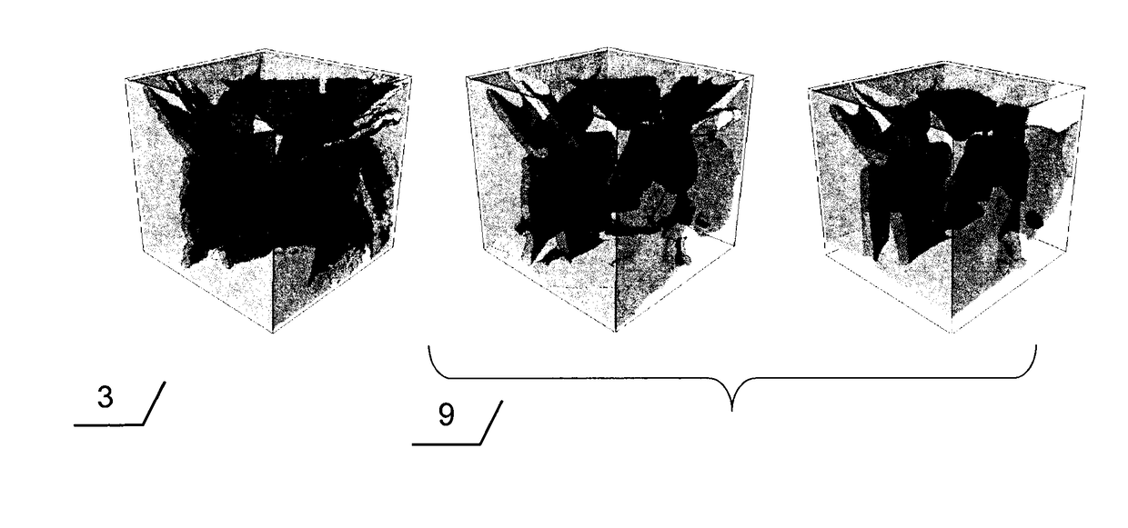
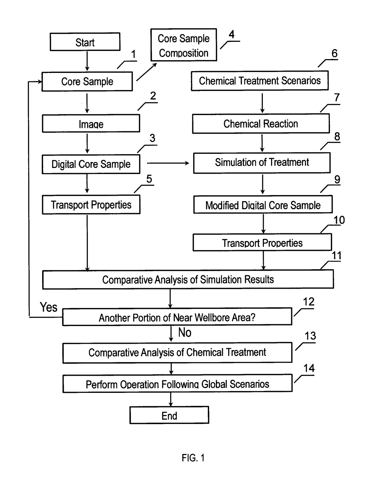
The patent is about a method for treating a near wellbore area by extracting a core sample from the area and analyzing it to get information about the mineral composition and the pore space structure. This information is then used to create a 3D model of the pore space and simulate the flow of fluids through it. Various scenarios for chemical treatment of the area are then created and the rates of chemical reactions between the treatment fluid and the minerals are calculated. The results of the simulations are compared to decide on the best chemical treatment scenario for the near wellbore area. The technical effect of this patent is a better understanding of the pore space structure of the near wellbore area and the ability to optimize chemical treatment for the area.

Problems solved by technology

Chemistry of oil bearing rock, damage and reservoir fluids can be too complex and hence the choice of a treatment fluid in each particular case is far from obvious.
In spite of progress achieved in acidizing technique there are still a lot of uncertainties regarding influence of treatment fluids on the properties of a near wellbore area.
Significant drawback of such an approach is that laboratory tests are destructive, which means that tests cannot be repeated on the same rock sample under the same condition.
Besides, there are smaller uncertainties in selection of fluids for single or multistage treatment.

Method used


Image

  • A method and a system for performing chemical treatment of a near wellbore area
  • A method and a system for performing chemical treatment of a near wellbore area
  • A method and a system for performing chemical treatment of a near wellbore area

Examples


Embodiment Construction

[0019]Specific embodiments will now be described in detail with reference to the accompanying figures.

[0020]In the following detailed description of one or more embodiments, numerous specific details are set forth in order to provide a more thorough understanding. However, it will be apparent to one of ordinary skill in the art that embodiments may be practiced without these specific details. In other instances, well-known features have not been described in detail to avoid unnecessarily complication of the description.

[0021]In general, embodiments provide a method and system for analyzing multiple chemical agents on a single core sample or set of core samples with regard to its application for chemical treatment of a near wellbore area.

[0022]Chemical treatment of a near wellbore area, as used in this application, refers to a technique improving the performance of a particular well. Fluids can be injected to a production well or an injection well.

[0023]Chemical well treatment affect...


PUM


Abstract

Performing of a chemical treatment of a near wellbore area may include extraction of a core sample representing a portion of a near wellbore area, obtaining a three-dimensional (3D) pore scale model of a core sample, determination of composition of a core sample, generation scenarios of chemical treatment that each include chemical agent, determination of rates of reaction between mineral comprising core sample and treatment fluids, determination of qualitative and quantitative composition of reaction system in equilibrium, simulation of chemical treatment process using 3D model of a core sample and data on chemical reactions between minerals and treatment fluids, analysis of the chemical treatment influence on transport properties of a core sample, selection of optimal treatment scenario. Further, an operation is performed using the selected treatment scenario.

Description

FIELD OF THE INVENTION[0001]This disclosure relates generally to the field of chemical treatment of hydrocarbon producing wells. More specifically, the disclosure relates to methods for performing chemical treatment involving injection of chemicals into a well.BACKGROUND OF THE INVENTION[0002]Properties of a near wellbore area largely determine performance of a particular well, specifically a rate of hydrocarbon recovery and well operation costs. A term “properties of a near wellbore area” refers in this application to porosity and permeability of a near wellbore area. The properties of a near wellbore area can be altered by but not limited to drilling and completion fluids, precipitation products and fines migrating from a formation to a borehole. Modification of the properties of a near wellbore area can be required on a stage of starting of well operation as well as during well operation. One of approaches to modify the properties of a near wellbore area is based on injection of ...

Claims


Application Information

Patent Timeline
Patent Type & Authority Applications(United States)
IPC IPC(8): E21B43/28G06T15/08E21B43/25E21B43/16
CPCE21B43/28G06T15/08E21B43/25E21B43/162G06T17/05G06T2207/10081
Inventor DINARIEV, OLEG YURYEVICHEVSEEV, NIKOLAY VYACHESLAVOVICHZIAUDDIN, MURTAZASAFONOV, SERGEY SERGEEVICHBELETSKAYA, ANNA VYACHESLAVOVNAKLEMIN, DENIS VLADIMIROVICHKOROTEEV, DMITRY ANATOLIEVICH
Owner SCHLUMBERGER TECH CORP
Learn More