
Method for manufacturing high-silicon steel strip by continuous siliconizing

a technology of high-silicon steel and siliconizing, which is applied in the direction of manufacturing tools, heat treatment equipment, furnaces, etc., can solve the problems of deterioration in the surface quality of steel strips, and it is not possible to efficiently manufacture high-silicon steel strips having good surface quality, so as to improve the reaction efficiency of treatment gas, prevent deterioration in the surface quality of steel strips, and efficiently manufacture high-silicon steel strips

Active Publication Date: 2018-08-30
JFE STEEL CORP
View PDF0 Cites 0 Cited by
  • Summary
  • Abstract
  • Description
  • Claims
  • Application Information

AI Technical Summary

Benefits of technology

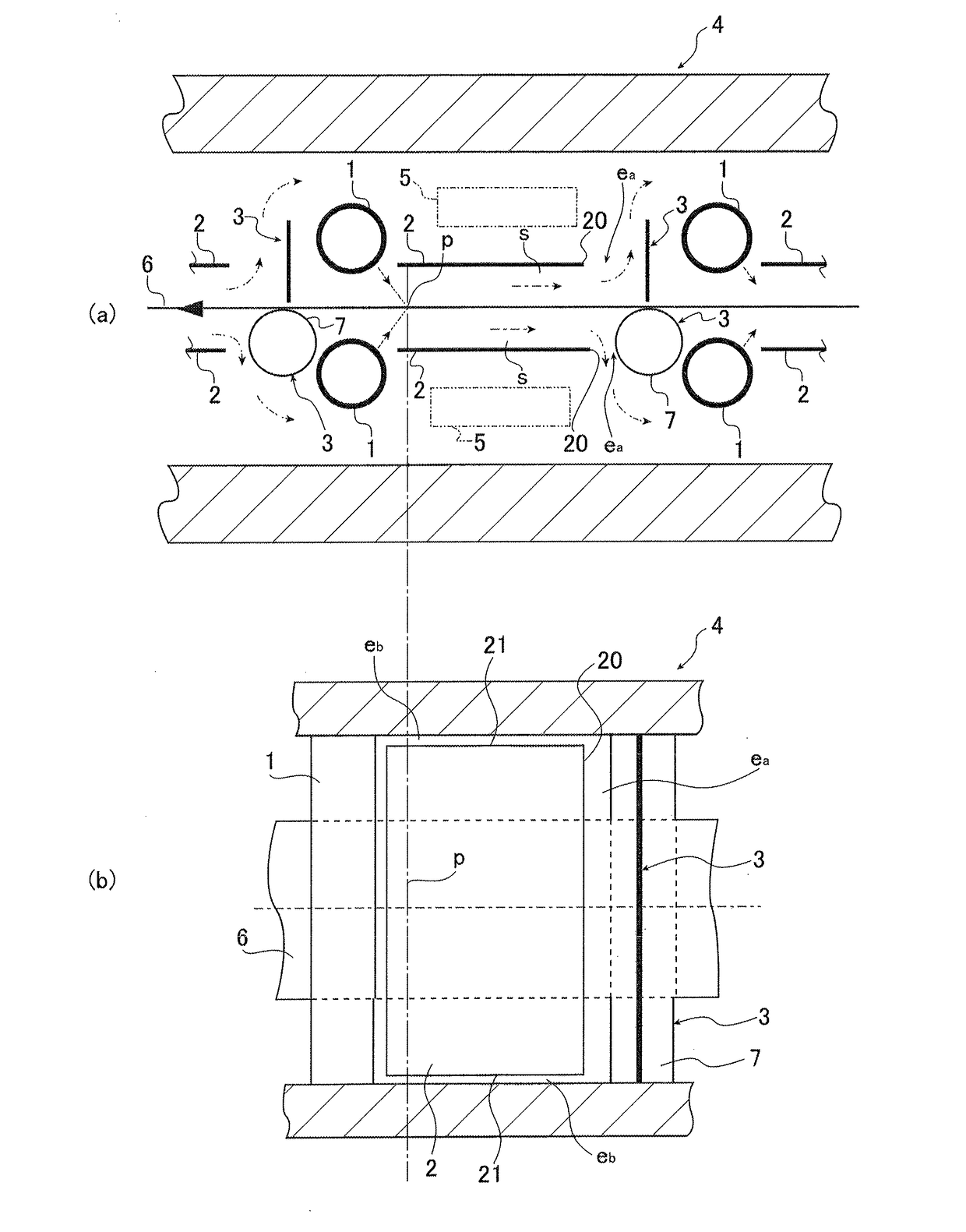
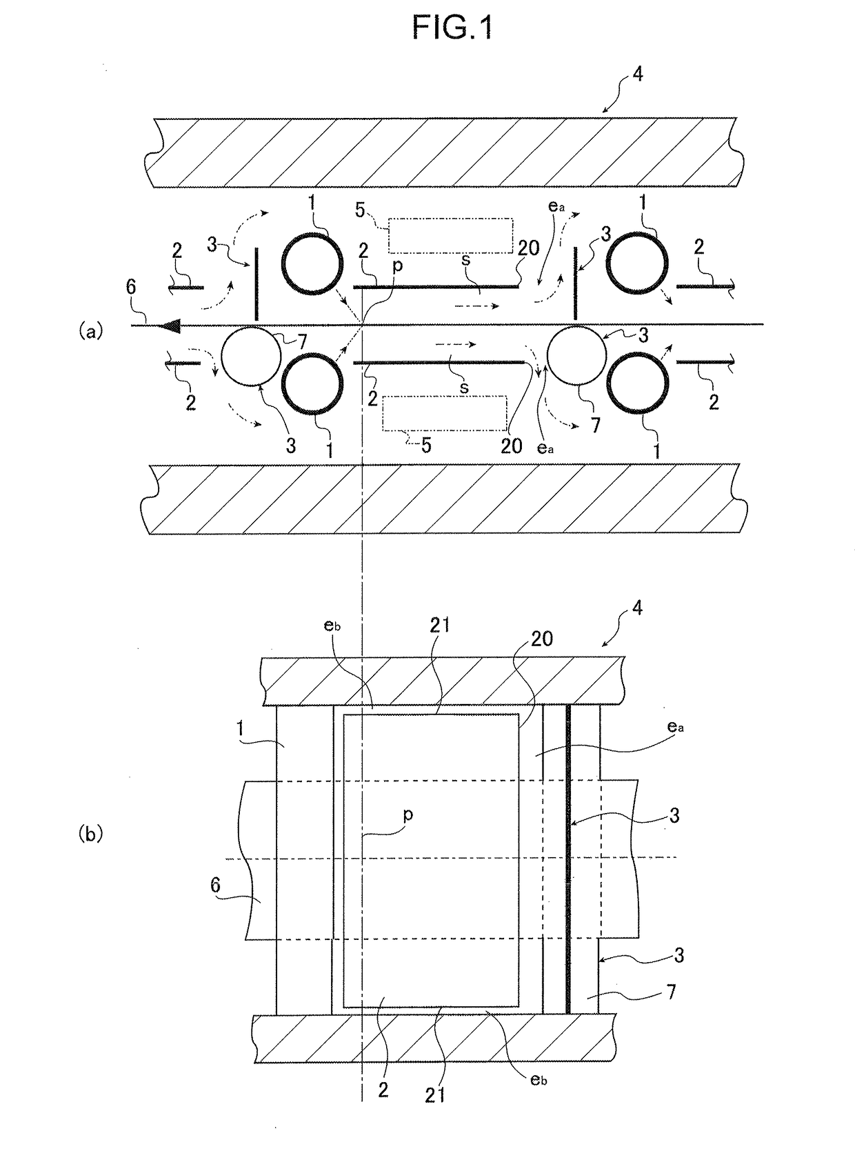
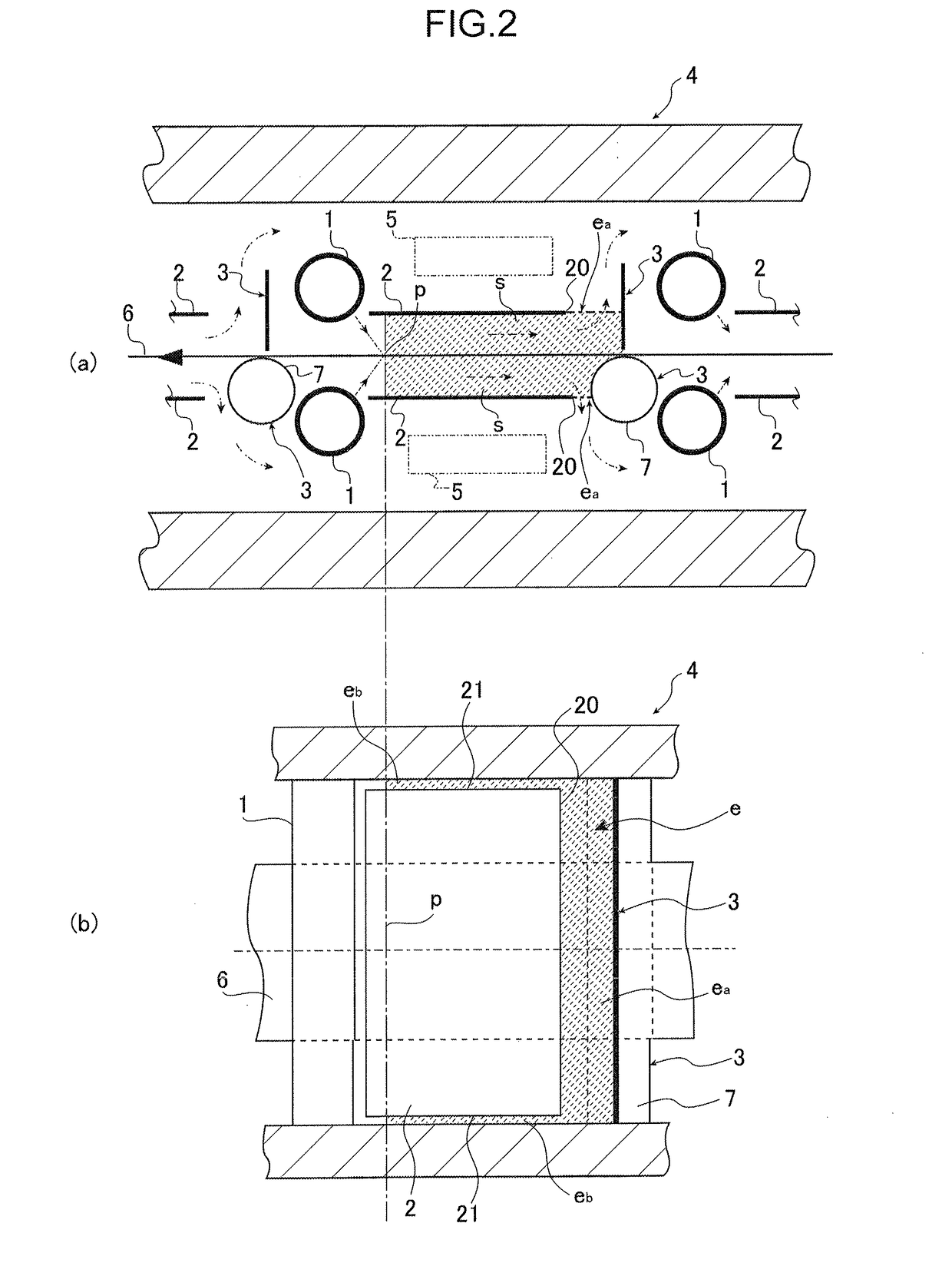
The present invention provides a method for efficiently manufacturing high-silicon steel strips with excellent surface quality by increasing the reaction efficiency of treatment gas and appropriately discharging by-products generated by siliconizing reaction from the siliconizing spaces to prevent deterioration in the surface quality of the steel strip. This is achieved by optimizing the relationship between the volume of siliconizing spaces and the area of exhaust passages to discharge treatment gas and by-products through the exhaust passages.

Problems solved by technology

However, in the case where a siliconizing space is formed by partition plates in a furnace, if it is not possible to appropriately discharge by-products generated by a siliconizing reaction from the siliconizing space, iron in the treatment gas which have been replaced with silicon adhere again to the surface of the steel strip, causing a problem of a deterioration in the surface quality of the steel strip.
Therefore, in the case where a partition plate is simply placed as in the case of Patent Literature 1, it is not possible to efficiently manufacture a high-silicon steel strip having good surface quality, because it is not possible to satisfy the following requirements at the same time, that is, requirement (i) that the reaction efficiency of treatment gas be increased and requirement (ii) that good surface quality of a steel strip be achieved.

Method used


Image

  • Method for manufacturing high-silicon steel strip by continuous siliconizing
  • Method for manufacturing high-silicon steel strip by continuous siliconizing
  • Method for manufacturing high-silicon steel strip by continuous siliconizing

Examples


examples

[0059]By performing a siliconizing treatment on steel strips (3.0-mass %-Si containing materials) having a thickness of 0.1 mm by treatment gas containing SiCl4 in a continuous siliconizing furnace having the equipment configuration illustrated in FIG. 1, high-silicon steel strips (6.5-mass %-Si materials) were manufactured. At that time, the total volume Vs of siliconizing spaces s and the total area So of exhaust passages e were changed, and the reaction efficiency of the treatment gas and the surface quality of the high-silicon steel strip manufactured were investigated. The results are given in Table 1.

[0060]Here, it is particularly desirable that the reaction efficiency be 0.2 or more. On the other hand, in the case where the reaction efficiency is less than 0.1, there is a significant decrease in efficiency and an increase in cost from the viewpoint of industrial production. Therefore, a case of a reaction efficiency of 0.20 or more was judged as “Excellent”, a case of a react...


PUM

PropertyMeasurementUnit
total areaaaaaaaaaaa
total volumeaaaaaaaaaa
lengthaaaaaaaaaa

Abstract

A high-silicon steel strip is manufactured. A basic configuration includes partition plates arranged in the longitudinal direction of a furnace to extend from a position in the vicinity of respective gas nozzles to be in parallel to the pass line of the steel strip, and obstacles arranged to face partition-plate rear edges in the longitudinal direction of the furnace to obstruct the flow of the gas along the steel strip so that siliconizing spaces surrounded by the steel strip, the partition plates, and the obstacles are formed; and gaps between the partition-plate rear edges and the obstacles and so forth which form exhaust passages through which gas is discharged from the siliconizing spaces to other spaces inside the furnace so that treatment gas which has been sprayed from the gas nozzles onto a surface of the steel strip to flow through the siliconizing spaces is discharged through the exhaust passages.

Description

CROSS REFERENCE TO RELATED APPLICATIONS[0001]This is the U.S. National Phase application of PCT / JP2016 / 003987, filed Sep. 1, 2016, which claims priority to Japanese Patent Application No. 2015-176485, filed Sep. 8, 2015, the disclosures of these applications being incorporated herein by reference in their entireties for all purposes.TECHNICAL FIELD OF THE INVENTION[0002]The present invention relates to a method for manufacturing a high-silicon steel strip by performing a siliconizing treatment on a steel strip in a continuous siliconizing furnace.BACKGROUND OF THE INVENTION[0003]A high-silicon steel sheet is often used for iron cores of transformers and motors because such a steel sheet has an excellent high-frequency magnetic property represented by, for example, low iron loss and high magnetic permeability. In particular, it is known that a high-silicon steel sheet exhibits an excellent high-frequency magnetic property such as a magnetostriction quantity of 0 and the peak value of...

Claims


Application Information

Patent Timeline
Patent Type & Authority Applications(United States)
IPC IPC(8): C23C10/08C23C10/02C21D9/46
CPCC23C10/08C23C10/02C21D9/46C21D9/56
Inventor KASAI, SHOJIDOI, TAKASHINISHIDE, MASATOSHI
Owner JFE STEEL CORP
Learn More