
Handheld surgical instrument

a surgical instrument and hand-held technology, applied in the field of hand-held surgical instruments, can solve the problems of poor microfracture results, poor microfracture results, and difficulty in microfracture procedures with a minimum of two operators, so as to improve the effectiveness of procedures, improve the clinical results of microfracture, and improve the effect of the procedur

Active Publication Date: 2018-08-30
MFR TECH INC
View PDF2 Cites 11 Cited by
  • Summary
  • Abstract
  • Description
  • Claims
  • Application Information

AI Technical Summary

Benefits of technology

The invention is a novel instrument for use in microfracture procedures and other bone marrow access procedures. It can be operated using one hand, solving the problem of multiple operators having to use separate tools. The device can access bone at multiple angles and deliver a precise load and direction to the tip, resulting in better controlled hole size, shape, and depth. The instrument also has a disposable tip which can increase its sharpness when used. The invention comprises six main parts, including a master energy storage element, an impact mechanism, a power transmission mechanism, a tip, a means of energy input, and a trigger mechanism. Two or more parts may be combined in a direct drive configuration, for example.

Problems solved by technology

Reported clinical results of microfracture are very good in some cases, but other researchers have reported relatively poorer results.
As such, a problem exists in that at least three hands are required to perform such a procedure using the historically accepted method.
While each tool must be operated with careful precision, and the feedback from each tool is interdependent, coordinating a microfracture procedure with a minimum of two operators presents a challenge.
There are several technical challenges associated with the creation of microfracture holes in the bone.
This can result in a highly variable amount of force being applied, resulting in unpredictable hole size and depth.
In addition, excessive load can cause significant bone edema, pain and loss of function in patients.

Method used


Image

  • Handheld surgical instrument
  • Handheld surgical instrument
  • Handheld surgical instrument

Examples


Embodiment Construction

[0067]In the following description, reference is made to the accompanying drawings that form a part hereof, and in which is shown by way of illustration various embodiments in which the invention may be practiced. It is to be understood that other embodiments may be utilized, as structural and operational changes may be made without departing from the scope of the present invention. The following detailed description, therefore, is not to be taken in a limiting sense, and the scope of the invention is defined by the appended claims.

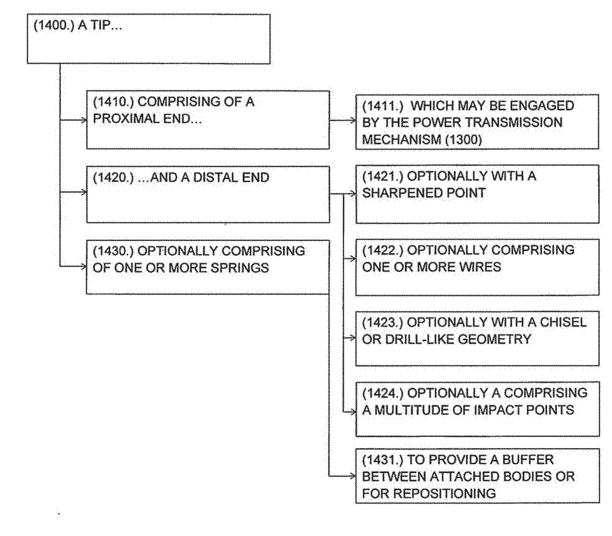
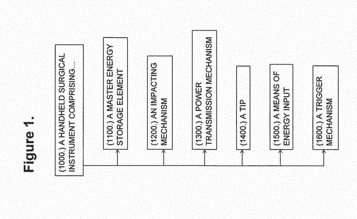
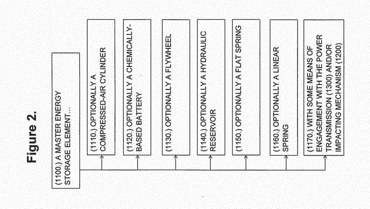
[0068]The present invention comprises a handheld surgical instrument for creating holes in tissue. The instrument comprises six main parts, including a master energy storage element (1100); an impact mechanism (1200); a power transmission mechanism (1300); a tip (1400); a means of energy input (1500); and a trigger mechanism (1600).

[0069]In one embodiment, the master energy storage element (1100) is a flat coil spring wound around two cylinders, one cylin...


PUM


Abstract

A handheld surgical instrument comprising an energy storage element, wherein the energy storage element is a spring coupled to the impacting mechanism, an impacting mechanism has a tip configured to impact a bone, wherein the tip includes a tapered point, a power transmission mechanism is configured to transmit energy from the energy storage element to the impacting mechanism, wherein the power transmission mechanism includes a semi-flexible metal wire guided by a hollow shaft, wherein the hollow shaft includes a distal end, the semi-flexible metal wire is includes a bend toward the distal end, a trigger mechanism is configured to release energy from the energy storage element, wherein the bend includes an angle between 14 degrees and 46 degrees, wherein the trigger mechanism includes a manual lever which, when actuated, simultaneously retracts the tip and charges the energy storage element.

Description

CLAIM OF PRIORITY[0001]This application claims priority to U.S. Provisional Patent Application Ser. No. 62 / 464,614 filed Feb. 28, 2017 and U.S. Provisional Patent Application Ser. No. 62 / 596,420 filed Dec. 8, 2017, both of which are herein incorporated by reference.FIELD OF THE INVENTION[0002]The present invention is generally directed to a device for surgery, and more particularly, for accessing bone marrow for enhancement of tissue repair. One popular example use is performing automated microfracture on subchondral bone to repair articular cartilage. Other examples include the stimulation of healing in areas of tendinosis such as elbow lateral epicondylitis, patella tendinopathy, hip gluteus medius tendinopathy, and ankle achilles tendinitis; to stimulate ligament healing such as in knee medial collateral ligament sprains; to enhance soft tissue to bone healing such as in the repair of the shoulder rotator cuff tendon to bone; for the enhancement of bony healing in fractures; and ...

Claims


Application Information

Patent Timeline
Patent Type & Authority Applications(United States)
IPC IPC(8): A61B17/16
CPCA61B17/1631A61B17/1622A61B17/1637A61B2017/00734A61B2017/00473A61B2017/00411A61B17/1604A61B2017/924
Inventor LAUGHLIN, TREVOR JACOBKOH, JASON L.FISHER, DANIEL M.BEAUBIEN, BRIAN PHILIPSALADINO, JOSEPH JUDE
Owner MFR TECH INC
Learn More