
A gaze tracker and a gaze tracking method

a technology of gaze tracking and tracking method, which is applied in the field of gaze tracking and gaze tracking method, can solve the problem of improving the accuracy of the gaze tracking device, and achieve the effect of lowering the light intensity of the light elemen

Inactive Publication Date: 2018-08-23
ITU BUSINESS DEV AS
View PDF2 Cites 23 Cited by
  • Summary
  • Abstract
  • Description
  • Claims
  • Application Information

AI Technical Summary

Benefits of technology

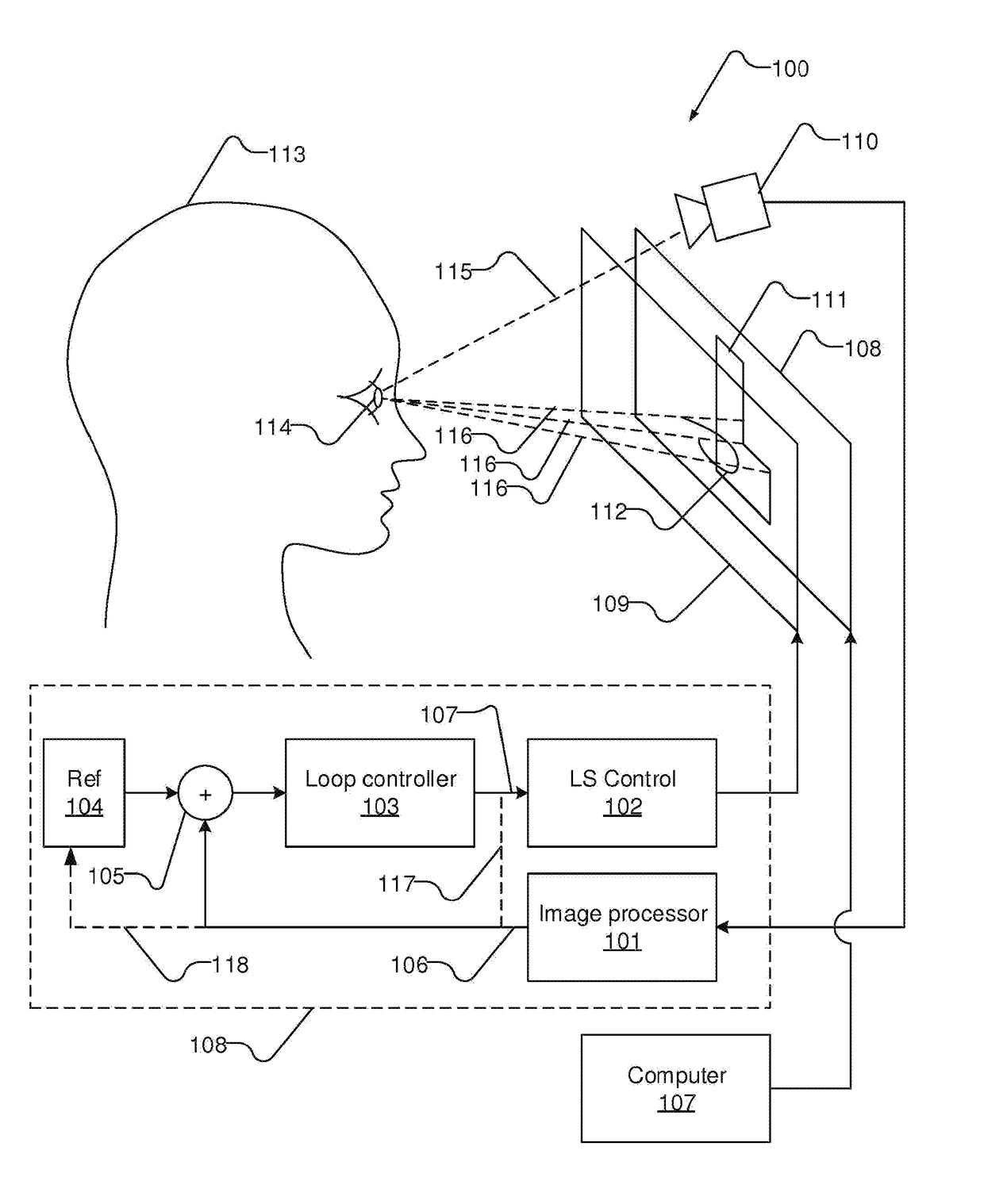
The present invention has the advantage of reducing or maintaining the gaze error at a low level. This is achieved by properly deactivating the light elements to avoid a trace of light patterns across several loop steps or to intentionally desire a trace of light patterns. The light elements can be activated at one, two, three, or a limited number of positions of light patterns, and their intensity can be gradually lowered to achieve the desired effect.

Problems solved by technology

However, it still remains a problem how to improve accuracy of a gaze tracker.

Method used


Image

  • A gaze tracker and a gaze tracking method
  • A gaze tracker and a gaze tracking method
  • A gaze tracker and a gaze tracking method

Examples


first embodiment

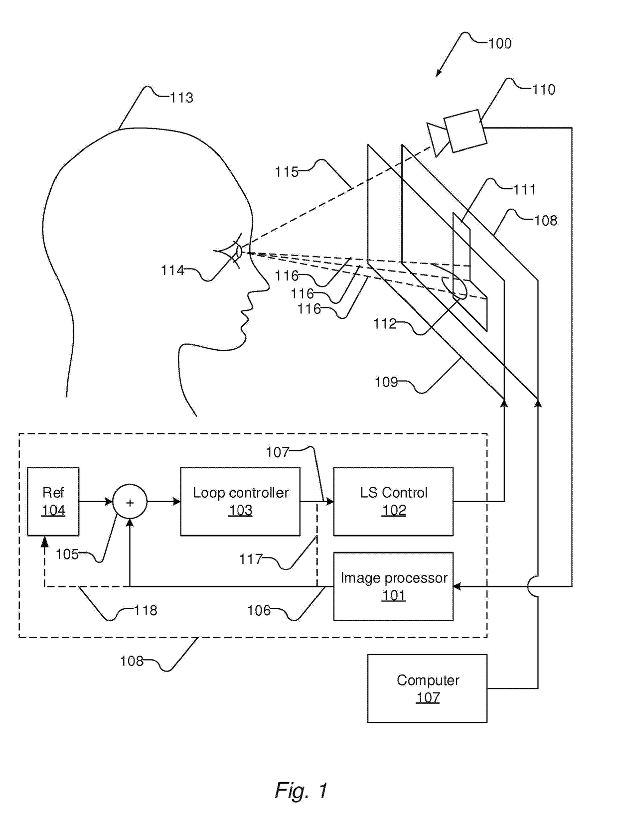
[0115]FIG. 2 shows, in a first embodiment, light emitted from light elements of the light source 109 at infrared wavelengths and light emitted from light elements of a computer display at visible wavelengths. The light source 109 constitutes a layer in front of the computer display 108, wherein the light source 109 and the computer display 108 largely spans the same area.

[0116]The light elements of the computer display are generally designated by reference numeral 205. The computer display 108 is illustrated by a frame 202 wherein some light elements emits light to display a shape 204 in the form of a capital as illustrated by hatching.

[0117]Turning to the light source, illustrated by a frame 203, the light elements of the light source are generally designated by reference numeral 206, wherein light elements that emit light is shown in solid black. Firstly, in this exemplary illustration, the light pattern is generated by one of the light emitting elements at a point in time as illu...

second embodiment

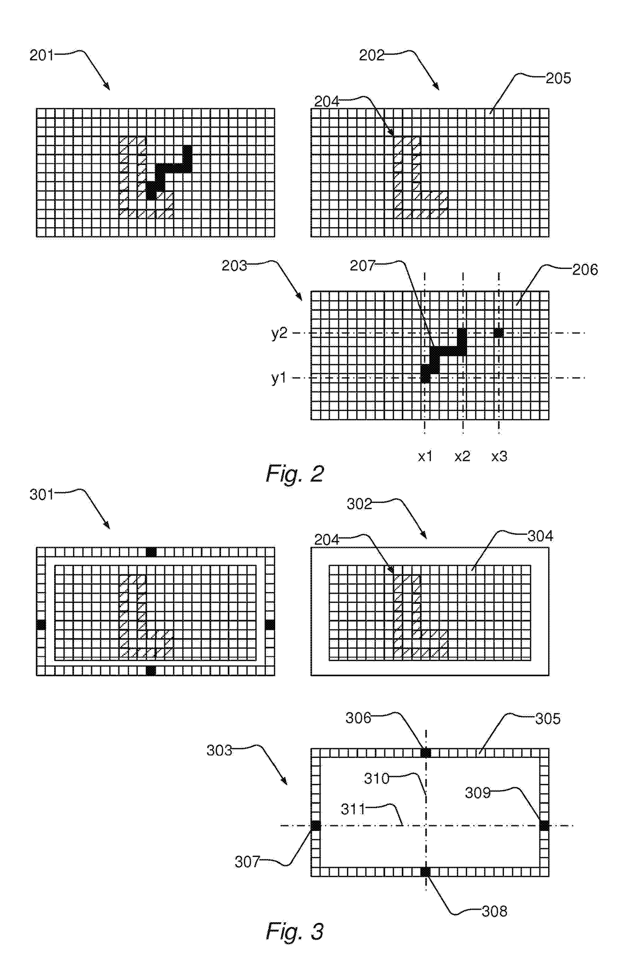
[0120]FIG. 3 shows, in a second embodiment, light emitted from light elements of the light source 109 at infrared wavelengths and light emitted from light elements of a computer display 108 at visible wavelengths. In this embodiment, the light source is configured as elongated arrays of light elements arranged along the periphery of the computer display or along one or more edges thereof.

[0121]The light elements of the computer display are generally designated by reference numeral 304. The computer display is illustrated by a frame 302 wherein some light elements emits light to display a shape 204 in the form of a capital as illustrated by hatching.

[0122]Turning to the light source, illustrated by a frame 303, the light elements of the light source are generally designated by reference numeral 305, wherein light elements that emit light is shown in solid black. Since the light source is arranged adjacent to the computer display, e.g. along the periphery of the computer display, the ...


PUM


Abstract

A gaze tracker and a computer-implemented method for gaze tracking, comprising the steps of: recording video images of a being's eye such that an eye pupil and a glint on the eye ball caused by a light source ( ) are recorded; processing the video images to compute an offset between the position of the predetermined spatial feature and a predetermined position with respect to the glint; by means of the light source such as a display, emitting light from a light pattern at a location selected among a multitude of preconfigured locations of light patterns towards the being's eye; wherein the location is controlled by a feedback signal; controlling the location of the light pattern from one location to another location among the predefined locations of light patterns, in response to the offset, such that the predetermined position with respect to the glint caused by the light source tracks the predetermined spatial feature of the being's eye; wherein the above steps are repeated to establish a control loop with the location of the light pattern being controlled via the feedback signal.

Description

[0001]Eye-tracking also denoted gaze estimation is an evolving technology that is becoming integrated in consumer products such as personal computers, laptop computers, tablet computers, smart phones, and other devices like for instance Wearable Computing Devices, WCDs comprising Head-Mounted Displays, HMDs.[0002]However, there still exist problems in how to improve the accuracy of gaze trackers such that a user's gaze can be accurately and reliably computed.RELATED PRIOR ART[0003]U.S. Pat. No. 7,686,451 discloses a camera-based gaze tracker with a motorized gimbal mount for continuously pointing and focussing the camera on a user's eye. Thereby the camera moves as the user moves his head and it is thereby possible to increase the gaze tracker's tolerance to head motion. The camera is moved side-to-side and up-and-down via the motorized gimbal mount which is controlled by a direction-control loop that uses image processing software to track the movements of the eye. The direction-co...

Claims


Application Information

Patent Timeline
IPC IPC(8): G06F3/01H04N5/235G06T7/73H04N5/33G02B27/01
CPCG06F3/013H04N5/2354G06T7/74H04N5/33G02B27/0172G06T2207/30041G02B2027/0138G06T2207/10016G02B2027/014A61B3/113H04N23/20H04N23/74
Inventor MARDANBEGI, DIAKOHANSEN, DAN WITZNER
Owner ITU BUSINESS DEV AS
Learn More