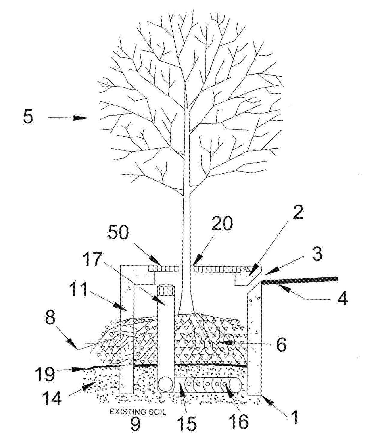
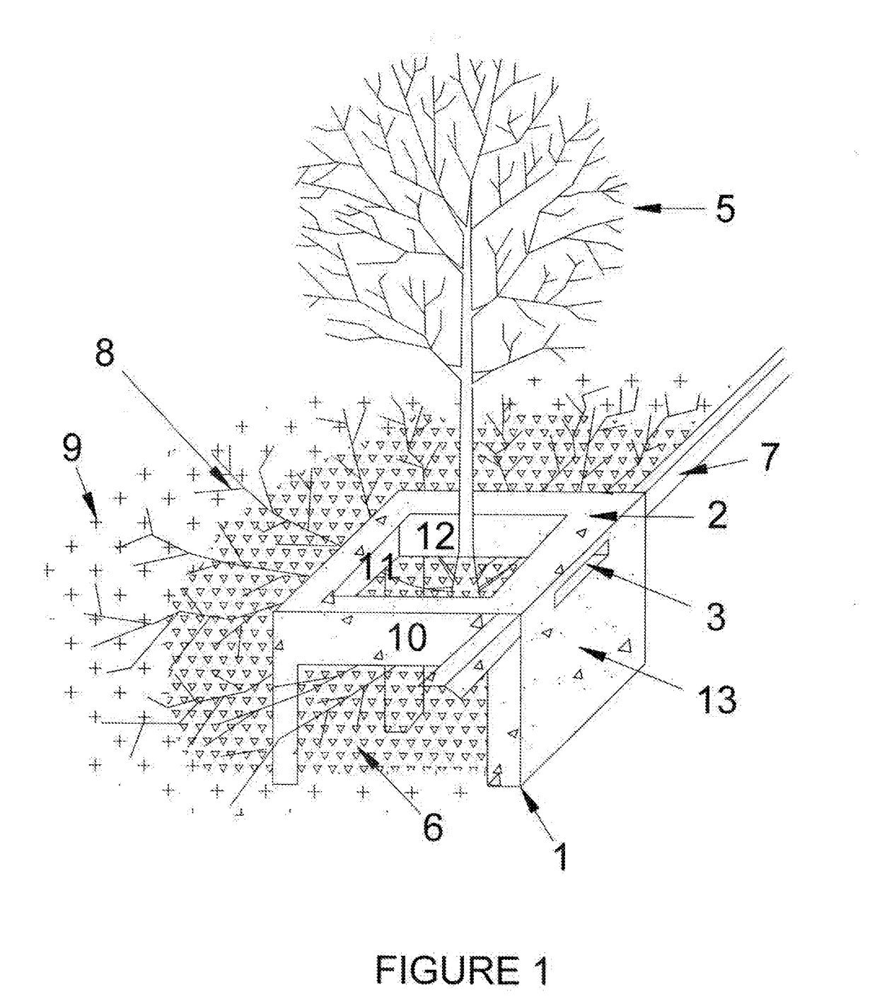
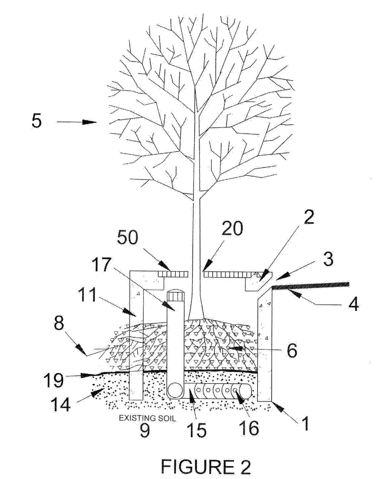
Tree Frame and Grate System and Method to Improve Growth of Vegetation in an Urban Environment
a technology of grate and tree frame, which is applied in the direction of single unit paving, lighting and heating equipment, roads, etc., can solve the problems of affecting the planting soil, buried rubble and debris from previous activities, and severe compaction of existing soil, so as to encourage encourage collection and retention of rainwater, and encourage the effect of healthy and abundant root growth
- Summary
- Abstract
- Description
- Claims
- Application Information
AI Technical Summary
Benefits of technology
Problems solved by technology
Method used
Image

Examples
Embodiment Construction
Definitions
[0035]The following terms are defined to aid the reader in fully understanding the operation, function, and utility of the present invention.
[0036]“±5%” as used herein, refers to the possibility that the stated amount may vary by 5%. For instance, 100±5%, indicates that the claimed value may range from 95 to 105.
[0037]“And / or” as used herein, refers to the possibility that both items or one or the other are claimed. For instance, A and / or B refers to the possibility of A only, B only or both A and B are present in the claimed invention.
[0038]“Aggregate” as used herein, refers to a sum, mass, or assemblage of various loose particles of inorganic and / or organic matter of various size and dimension. Furthermore, an “aggregate matrix layer” would represent a distinct or discreet layer of the sum of one or more aggregates.
[0039]“ASTM” as used herein, refers to American Society for Testing Materials.
[0040]“Bioavailable” as used herein, refers to the extent to which a nutrient o...
PUM
| Property | Measurement | Unit |
|---|---|---|
| Power | aaaaa | aaaaa |
| Shape | aaaaa | aaaaa |
| Area | aaaaa | aaaaa |
Abstract
Description
Claims
Application Information
 - R&D
- Intellectual Property
- Life Sciences
- Materials
- Tech Scout
- Unparalleled Data Quality
- Higher Quality Content
- 60% Fewer Hallucinations
Browse by: Latest US Patents, China's latest patents, Technical Efficacy Thesaurus, Application Domain, Technology Topic, Popular Technical Reports.
© 2025 PatSnap. All rights reserved.Legal|Privacy policy|Modern Slavery Act Transparency Statement|Sitemap|About US| Contact US: help@patsnap.com