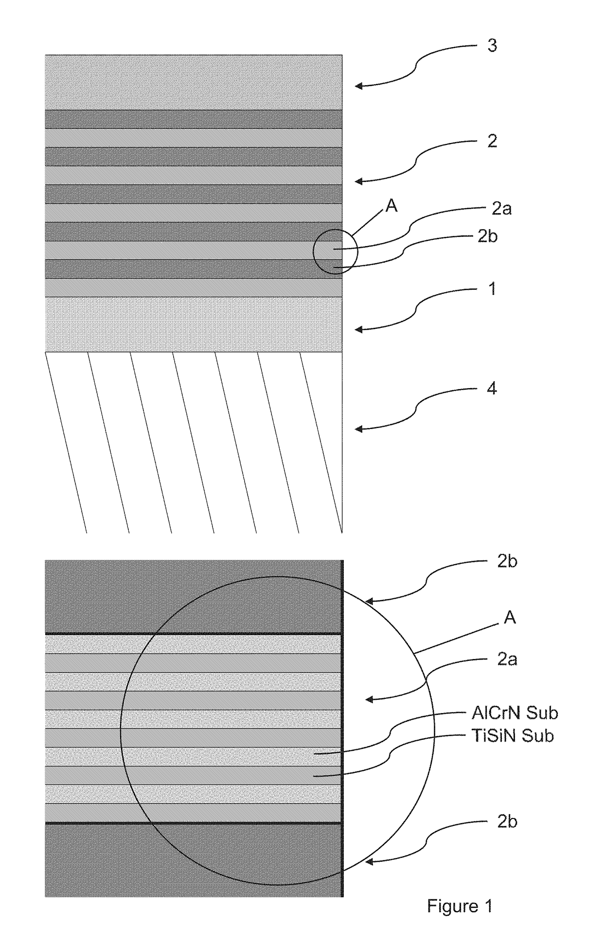
Tool with multi-layer arc pvd coating

a multi-layer arc arc and coating technology, applied in the direction of superimposed coating process, vacuum evaporation coating, coatings, etc., can solve the problems of increased tendency for oxidation, weakening of the coating, unsatisfactory roughness of the deposited coating, etc., to achieve high residual compressive stress, high coating thickness, and high hardness

Active Publication Date: 2018-08-09
WALTER AG
View PDF8 Cites 10 Cited by
  • Summary
  • Abstract
  • Description
  • Claims
  • Application Information

AI Technical Summary

Benefits of technology

[0005]There are commercially available tools having a PVD coating comprising a first multi-layer coat of TiN and TiAlN and a second multi-layer coat of TiSeN and AlCrN. The coating is deposited by two subsequent deposition processes to achieve a high coating thickness. After the deposition of the first multi-layer coat in a first deposition process the coated substrate is cooled down and subjected to a mechanical treatment wherein the residual compressive stresses of the first coat are changed, before the second multi-layer coat is then deposited in a further deposition process. The coating exhibits a high hardness, but, at the same time, also very high residual compressive stresses significantly above 3 GPa, which has a disadvantageous effect on the stability of the cutting edge, the uniform covering of the cutting edge and the performance of the tools.
[0006]WO 2006/041367 A1 describes a coated cutting tool consisting of a hard metal substrate and a coating which is deposited in the PVD process and comprises at least one coat of TiAlN having a thickness of 1.5 to 5 μm and a residual compressive stress >4 to 6 GPa. The TiAlN coat is said to adhere more effectively to the substrate compared with known coats. The very high residual compressive stresses have, however, a disadvantageous effect on the stability of the cutting edge.
[0007]EP 2 298 954 Al describes a method for producing a coated cutting tool wherein a hard material coating, ...

Problems solved by technology

Such droplets lead to undesired roughness of the deposited coating compared to coatings produced for example by magnetron sputtering.
In addition, the droplets result in a weakening of the coating, because in general they predominantly consist of pure metal and thereby exhibit a lower hardness and increased tendency for oxidation.
For specific metal machining operations, such as for example milling, turning and drilling, there exist particularly high demands on the tool.
If such TiAlN coatings are deposited by the arc vapor deposition process, they have a tendency for the formation of droplets on and in the coating due to the low melting temperature of the aluminum, which has a disadvantageous effect on the performance of the coating.
By appropriate selection of the parameters of the...

Method used


Image

  • Tool with multi-layer arc pvd coating
  • Tool with multi-layer arc pvd coating
  • Tool with multi-layer arc pvd coating

Examples


example 1

Production of Inventive Tools and Comparative Tools

[0059]In this example, substrates for solid hard metal (SHM) drills (SUB1), as well as for hard metal indexable cutting inserts (SUB2) were provided with inventive coatings and comparative coatings of the prior art.

[0060]Specification of the Solid Hard Metal (SHM) Drill (SUB1)[0061]Diameter: 8.5 mm[0062]Nominal drilling depth: 5×d[0063]Number of cutting edges: 2[0064]Length of cutting edges: 50% of the diameter[0065]Spiral angle of the flutes: about 30°[0066]Tip angle: 140°[0067]Substrate material: hard metal comprising 90 at-% WC, 9.2 at-% Co and 0.8 at-% Cr and having an average WC grain size of 0.7 μm

[0068]Specification of the Hard Metal Indexable Cutting Inserts (SUB2)[0069]Geometry: P6001[0070]Substrate material: hard metal comprising 88 at-% WC, 10.5 at-% Co and 1.5 at-% mixed carbides (TiC, TaC and NbC) and having an average WC grain size of about 5 μm

[0071]Specification of the Holder for the Hard Metal Indexable Cutting Inse...

example 2

Machining Tests

[0106]Tools produced according to example 1 were compared in machining tests (drilling).

[0107]Machining Test 1

[0108]Using solid hard metal drills (SUB1) having the coatings ERF2, VGL1, VGL2 and VGL3, respectively, blind holes of a depth of 18 mm were produced in an alloyed steel material, 42 CrMo4 (1.7225 according to EN10027-2) having a strength of 850 N / mm2 (vc=120 m / min; f=0.23 mm / U; internal cooling with KSS 5% and 20 bars).

[0109]The machining was terminated at an average flank wear of Vb>0.2 mm or a maximum flank wear Vbmax>0.25 mm, and the tool life distance reached until then was determined. The results are indicated in the following table 2 as the average tool life distance of three tests.

TABLE 2Average tool lifedistanceSubstrate / Coating[m]SUB1 / ERF232SUB1 / VGL110SUB1 / VGL215SUB1 / VGL322

[0110]Tools having the inventive coating reached significantly higher average tool life distances than the tools with the comparative coatings.

[0111]Machining Test 2

[0112]Using sol...


PUM

PropertyMeasurementUnit
Thicknessaaaaaaaaaa
Thicknessaaaaaaaaaa
Thicknessaaaaaaaaaa

Abstract

A tool includes a base body of hard metal, cermet, ceramics, steel or high speed steel and a multi-layer wear protection coating deposited thereon by a PVD process. The wear protection coating has a first coat deposited on the base body having a composition of TiaAl(1-a)N, wherein 0.4≤a≤0.6, and a coating thickness of 0.5 μm to 4 μm, and a second coat deposited on the first coat. The second coat includes a sequence of 10 to 80 first and second layers alternatingly arranged one on top of each other. Each of the first and second layers has a thickness of 5 to 100 nm. Each first layer includes nitrides of the elements Ti, Al, Cr and Si, and each second layer has a composition of TixAl(1-x)N, wherein 0.4≤x≤0.6. The first and second coats have up to 10 at-% of further metals, B, C and/or O as impurities in each layer.

Description

[0001]The invention relates to a tool with a main body made of hard metal, cermet, ceramic, steel or high-speed steel, and a multi-layer wear protection coating applied thereon by the PVD process. The wear protection coating comprises a first TiAlN coat and a second multi-layer coat above comprising the nitrides of the elements Ti, Al, Cr and Si. The invention further relates to a process for manufacturing the inventive tool, as well as the use thereof.BACKGROUND OF THE INVENTION[0002]Cutting tools, in particular tools for chip-forming metal machining, consist of a main body which is made for example of hard metal, cermet, ceramic, steel or high-speed steel. To increase the tool life or to improve the cutting properties, a single-layer or multi-layer wear protection coating made of hard materials is frequently applied to the main body by means of CVD or PVD processes. The PVD processes come in a number of different variants, such as magnetron sputtering, arc vapor deposition (arc PV...

Claims


Application Information

Patent Timeline
IPC IPC(8): C23C14/32C23C14/06C23C14/58
CPCC23C14/325C23C14/0641C23C14/5873C23C14/5886C22C29/08C23C28/044C23C28/042C23C28/42
Inventor ALBERS, ULRICHSCHIER, VEIT
Owner WALTER AG
Why Eureka
Try Eureka