
Aluminium composite material for use in thermal flux-free joining methods and method for producing same

a technology of aluminum composite materials and thermal flux-free joining, which is applied in the direction of manufacturing tools, solvents, transportation and packaging, etc., can solve the problems of deteriorating quality of solder connection, high installation cost, and use of corrosive or non-corrosive flux agents, and achieve flux-free joining good results, cost-effective

Inactive Publication Date: 2018-08-09
HYDRO ALUMINIUM ROLLED PROD GMBH
View PDF13 Cites 2 Cited by
  • Summary
  • Abstract
  • Description
  • Claims
  • Application Information

AI Technical Summary

Benefits of technology

This patent describes a special aluminum material that can be used in a flux-free thermal joining method without the need for expensive fluxing agents. The material contains a specific amount of magnesium (Mg) and a certain degree of surface treatment. By controlling the Mg content and surface treatment, the aluminum material can achieve outstanding solder results even without the use of fluxing agents. The use of this special aluminum material allows for the joining of components in a variety of joining methods, increasing flexibility and cost-effectiveness. Additionally, the material can be further improved by adding a small amount of bismuth (Bi) to enhance its solder properties.

Problems solved by technology

However, the use of corrosive or non-corrosive fluxing agents poses disadvantages, for example increased installation costs and technical problems during the interaction of remainders of the fluxing agent with for example coolant additives in a heat exchanger.
Furthermore, the use of fluxing agents is also problematic in relation to avoiding environmental impacts and from occupational safety points of view.
Lastly, in the CAB method, the use of Mg-containing solder alloys is problematic since magnesium negatively influences the solder properties under a protective gas atmosphere.
Magnesium interacts strongly with the fluxing agent, which is why said fluxing agent can no longer carry out its actual function and in the case of larger quantities of Mg soldering ultimately can no longer be carried out.
However, vacuum soldering installations are very costly both in terms of investment and also operation.
In vacuum soldering, however, the solder quality could be reduced as a result of residual gases and impurities in the atmosphere of the solder furnace reacting with the solder layer.
However, the disadvantage of this usually used high Mg content is that the condensate of the evaporated Mg is deposited as a residue in the furnaces.
As a result, the furnaces have to be expensively cleaned at shorter intervals to remove resulting residues.
This causes additional costs and reduces the productivity of the furnace installation.
A flux-free alternative to the CAB method is thus provided by vacuum soldering, however, vacuum soldering is very complex in terms of equipment and thus very cost-intensive.
The material selection was also previously limited due to the requirements of a higher Mg content.
Solder alloys with low Mg contents are in particular used in the CAB method using fluxing agents, however, they were previously hardly suitable for reliable and economic joining in the vacuum soldering method.
Solder alloys with higher Mg contents, roughly from 1.0 wt % Mg can be used in the vacuum with good solder results, but are entirely unsuitable for the CAB method.
The two-layer structure of the aluminium solder layer is, however, disadvantageous insofar as that during production of the two-layer aluminium solder layer, higher costs are incurred.
Furthermore, a significant disadvantage of conventional two-layer structures for example with an outer cladding of pure aluminium may be that its use is not compatible with fluxing agents.
Insufficient solder results, for example due to temporarily poorer furnace atmosphere with excessive oxygen partial pressure or excessive moisture in the atmosphere may not be optionally compensated by the use of fluxing agents.

Method used


Image

  • Aluminium composite material for use in thermal flux-free joining methods and method for producing same
  • Aluminium composite material for use in thermal flux-free joining methods and method for producing same
  • Aluminium composite material for use in thermal flux-free joining methods and method for producing same

Examples


Embodiment Construction

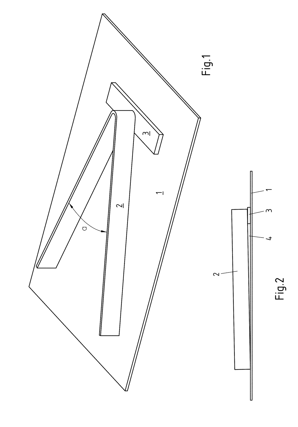
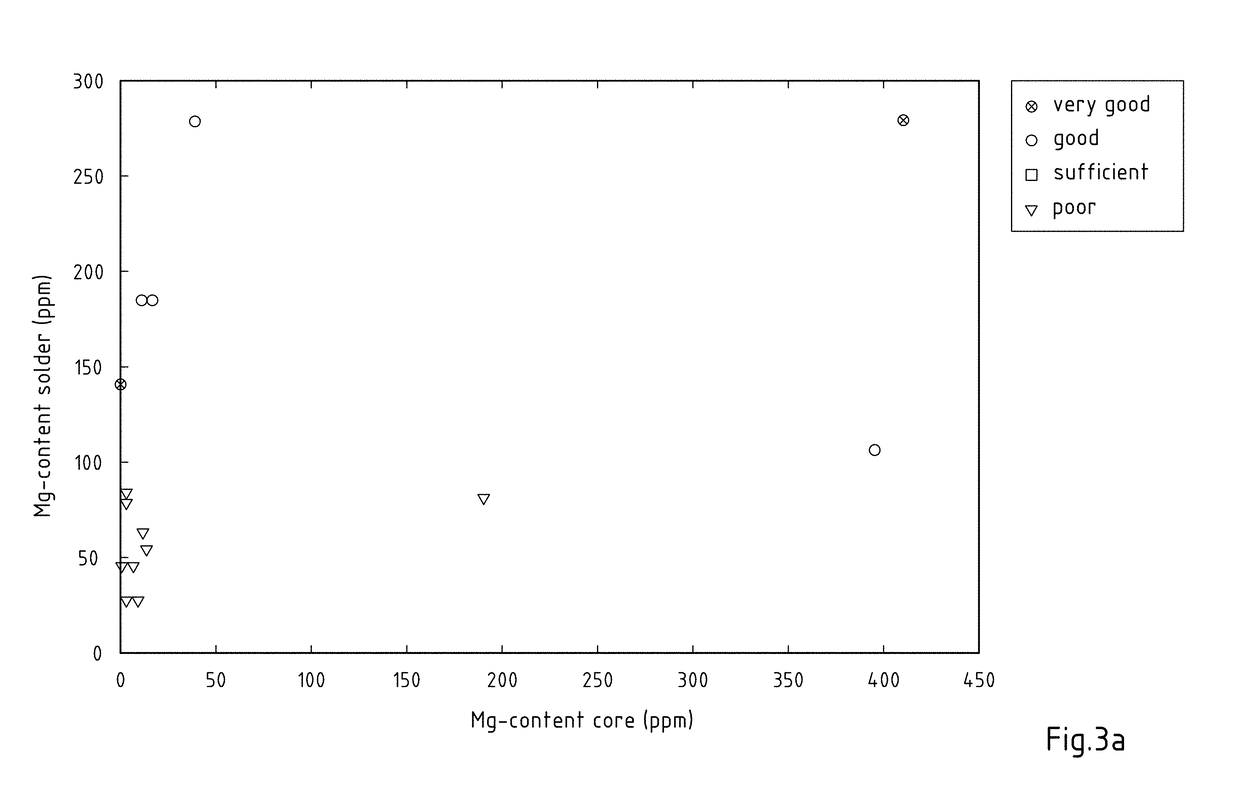
[0162]In order to examine the advantages of the aluminium composite material according to the invention, a number of tests have been carried out with a specified solder test arrangement, as is perspectively represented in FIG. 1. The solder test arrangement essentially consists of three parts in total, a sheet metal 1, an angular sheet metal 2 and a contact sheet metal 3 for the angular sheet metal 2. With its closed end 2a, the angular sheet metal 2 rests on the contact sheet metal 3 arranged on sheet metal 1. Both leg ends 2b, in contrast, rest on the sheet metal 1 such that, as represented in the side view in FIG. 2, a variable gap results from the contact point of the leg ends 2b of the angular sheet metal 2 to the contact point of the closed end 2a on the contact sheet metal 3. The solder gap 4 is increasingly larger from the angular ends 2b to the closed end 2a of the angular sheet metal. The increasing solder gap 4 means it can be determined to what extent the solder properti...


PUM

PropertyMeasurementUnit
Fractionaaaaaaaaaa
Fractionaaaaaaaaaa
Fractionaaaaaaaaaa

Abstract

Provided are embodiments of an aluminium composite material for use in thermal flux-free joining methods. The composite material has at least one core layer of an aluminium core alloy and at least one outer solder layer of an aluminium solder alloy. The aluminium solder alloy has the following composition in wt %: 6.5%≤Si≤13%, Fe≤1%, 230 ppm≤Mg≤450 ppm, Bi≤500 ppm, Mn≤0.15%, Cu≤0.3%, Zn≤3%, and Ti≤0.30% with the remainder Al and unavoidable impurities individually at most 0.05%, in total at most 0.15% and the aluminium solder layer has an alkaline pickled or acid pickled surface. The invention further relates to a method for producing an aluminium composite material, a method for the thermal joining of components, and a thermally joined construction.

Description

CROSS-REFERENCE TO RELATED PATENT APPLICATIONS[0001]This patent application is a continuation of PCT / EP2016 / 073667, filed Oct. 4, 2016, which claims priority to European Application No. 15188424.4, filed Oct. 5, 2015, the entire teachings and disclosure of which are incorporated herein by reference thereto.FIELD OF THE INVENTION[0002]The invention relates to an aluminium composite material for use in thermal flux-free joining methods, comprising at least one core layer consisting of an aluminium core alloy and at least one outer solder layer provided on one or both sides of the core layer consisting of an aluminium solder alloy. The invention further relates to a method for producing an aluminium composite material, in particular an aluminium composite material according to the invention in which at least one core layer consisting of an aluminium core alloy is provided and at least one outer solder layer consisting of an aluminium solder alloy is applied on one or both sides of the ...

Claims


Application Information

Patent Timeline
IPC IPC(8): B32B15/01B32B38/10B32B38/18B32B37/04
CPCB32B15/016B32B38/10B32B38/1858B32B37/04B32B2310/0418C22C21/06B23K35/286B23K35/288B23K35/0222B23K35/0233C22C21/00C22C21/02C22C21/04Y10T428/12764
Inventor ECKHARD, KATHRINGUSSGEN, OLAFRICHTER, THORSTENJANSSEN, HARTMUTEIGEN, NICO
Owner HYDRO ALUMINIUM ROLLED PROD GMBH
Learn More