Turbine component having multiple controlled metallic grain orientations, apparatus and manufacturing method thereof

Active Publication Date: 2018-07-19
GENERAL ELECTRIC CO
View PDF3 Cites 22 Cited by
  • Summary
  • Abstract
  • Description
  • Claims
  • Application Information

AI Technical Summary

Benefits of technology

The present invention relates to a turbine engine component comprising a first region with a first metallic grain orientation, a second region with a second metallic grain orientation, and one or more graded transition regions with a third metallic grain orientation. The gradient of the metallic grain orientation can be controlled to provide better performance of the turbine engine component. The invention also provides a method for making the component by irradiating layers of metallic powder to form the different regions with different metallic grain orientations. The components can be used in the turbine engine blades or stator vanes.

Problems solved by technology

Blade fatigue is a major source of failure in steam turbines and gas turbines.
Blade failures in gas turbine engines often lead to loss of all downstream stages and can have a dramatic effect on the availability of the turbine engines.
Fatigue is caused by the stress and strain induced by vibration and resonance within the operating range of machinery, which results in erosion and / or material build-up.
Even though they are stationary and function primarily to direct the stream propelled by the rotating blades to the next turbine stage, stator vanes which are also known as stator blades are nonetheless susceptible to fatigue.
However, the success of friction dampers in reducing the high dynamic stresses incurred by the blades and thereby prolonging their lives has been modest at best.
In some cases, the fatigue failures of the blade are even premature, occurring earlier than the calculated estimated lifetime of the blade.
Put simply, existing turbine engine components especially blades and vanes lack the tensile strength and ductility to withstand prolonged thermal-mechanical stress.
However, this reduction of grain size has not been shown to contribute to increased tensile strength of the manufactured article.
Such a process of altering and controlling the metallic grain orientation would be not only laborious, but simply impracticable when it comes to the manufacturing of modern and next generation turbine engines that require components and parts having increasingly intricate and complex geometries.
The rest of the blade, such as the airfoil which is also highly susceptible to fatigue, remains unstrengthened.

Method used


Image

  • Turbine component having multiple controlled metallic grain orientations, apparatus and manufacturing method thereof
  • Turbine component having multiple controlled metallic grain orientations, apparatus and manufacturing method thereof
  • Turbine component having multiple controlled metallic grain orientations, apparatus and manufacturing method thereof

Examples


Embodiment Construction

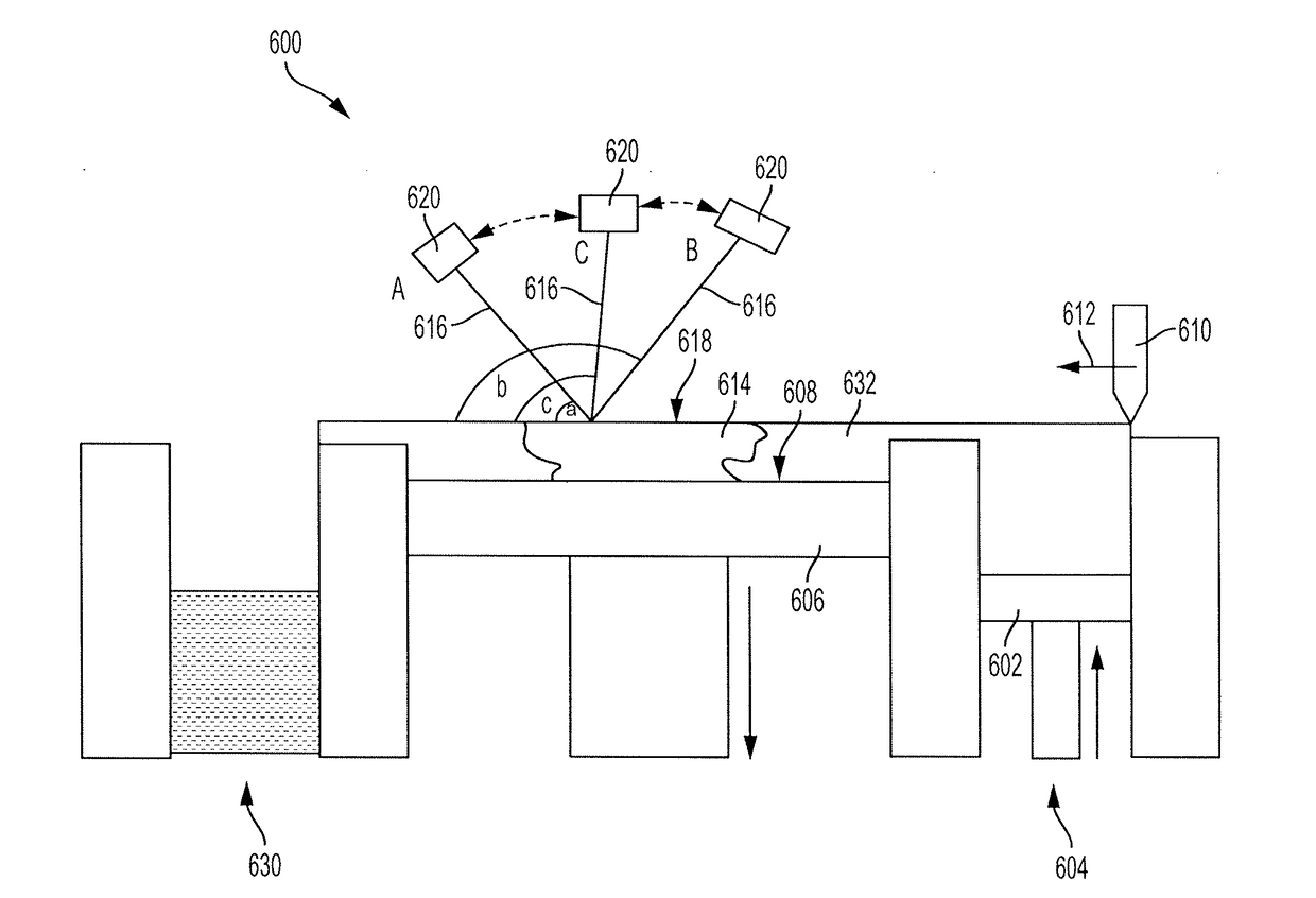
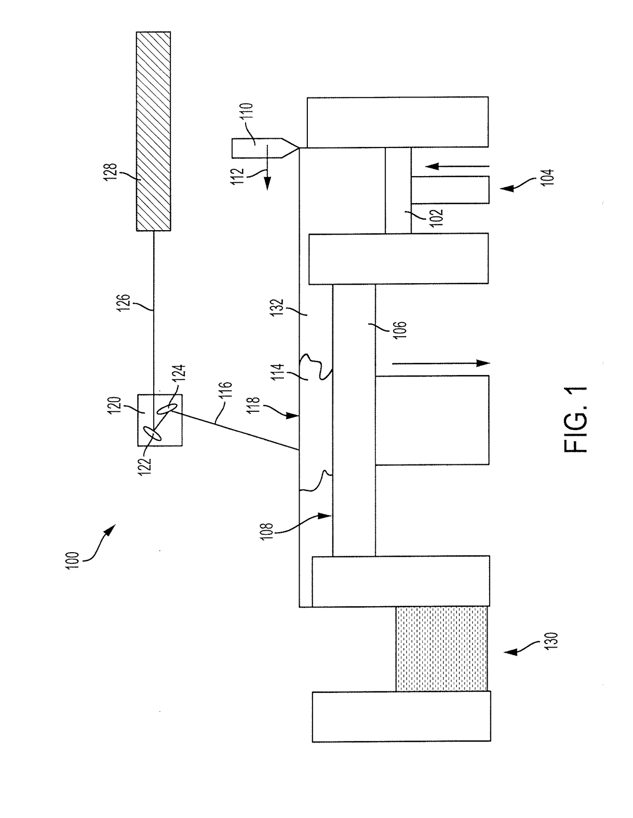
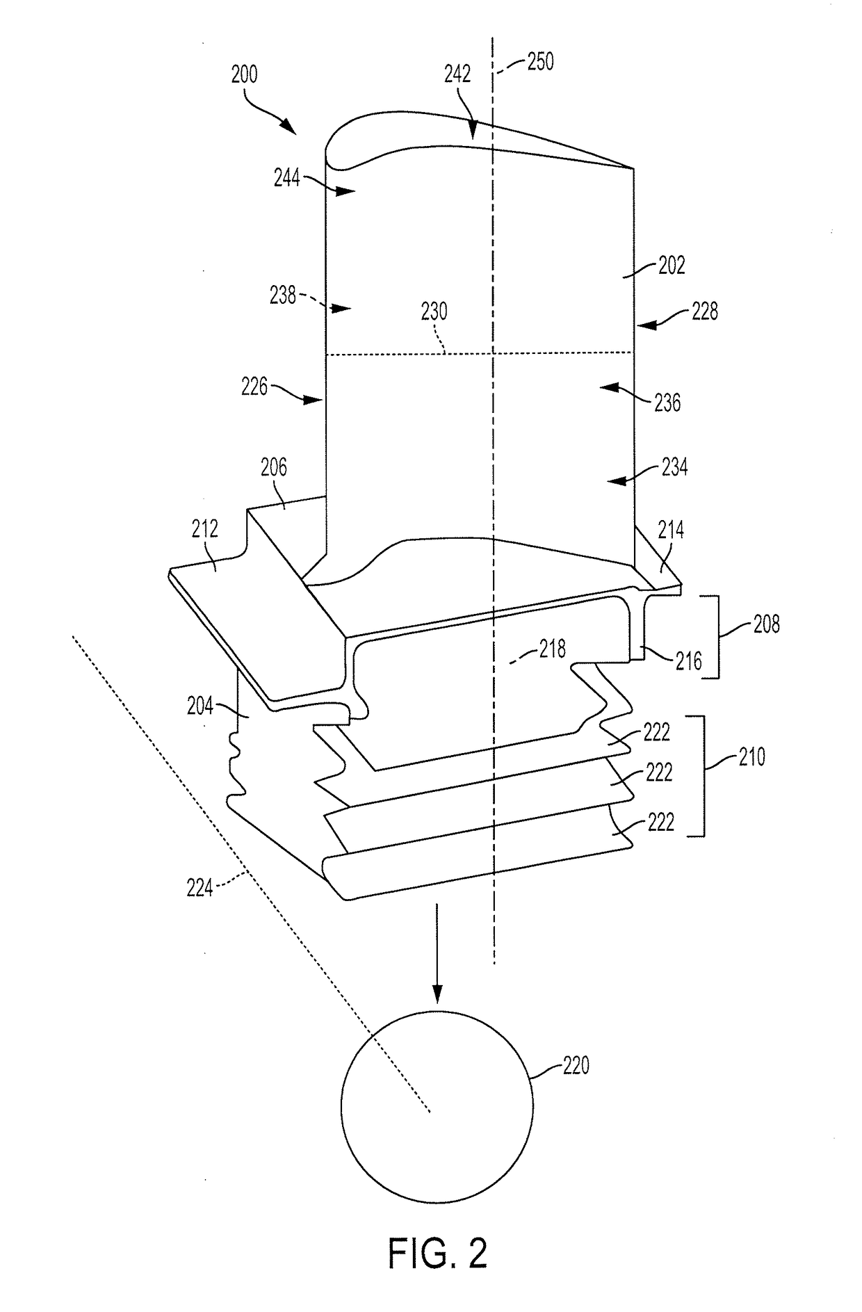
[0026]The detailed description set forth below in connection with the appended drawings is intended as a description of various configurations and is not intended to represent the only configurations in which the concepts described herein may be practiced. The detailed description includes specific details for the purpose of providing a thorough understanding of various concepts. However, it will be apparent to those skilled in the art that these concepts may be practiced without these specific details. For example, the present invention provides a preferred method for additively manufacturing metal components, and preferably these metal components are used in the manufacture of jet aircraft engines. Specifically, the production of single crystal, nickel-based superalloy or elemental titanium metal components such as turbine blades and stator vanes can be advantageously produced in accordance with this invention. However, other metal components of the turbine may be prepared using t...


PUM

PropertyMeasurementUnit
Thicknessaaaaaaaaaa
Thicknessaaaaaaaaaa
Metallic bondaaaaaaaaaa

Abstract

The present disclosure generally relates to turbine engine components having multiple controlled metallic grain orientations. In general, the primary grain orientation is aligned substantially perpendicular to the longitudinal axis of the turbine engine component while the secondary grain orientation is aligned substantially parallel to the longitudinal axis. Such controlled grain orientations provide the blades and vanes with increased strength to withstand the thermal-mechanical stresses of the turbine operation. The disclosure also relates to turbines having these fortified components, and methods of manufacturing the components.

Description

INTRODUCTION[0001]The present disclosure generally relates to a metal component having multiple controlled metallic crystal or grain orientations, an apparatus having the same and methods of manufacturing the same. More specifically, the metal component is prepared using an additive manufacturing (AM) method, which includes but is not limited to the direct metal laser melting (DMLM) or direct metal laser sintering (DMLS) method. The metal component produced is especially useful as a component of an aircraft engine or other power generation turbines, e.g. a turbine blade or a stator vane.BACKGROUND[0002]Additive manufacturing encompasses a variety of technologies for producing components in an additive, layer-wise fashion. These technologies can broadly be group into one of seven major classes based on the mechanism in which each layer is formed: photopolymerization, extrusion, sheet lamination, beam deposition, direct write and printing, powder bed binder jet printing, and powder be...

Claims


Application Information

Patent Timeline
IPC IPC(8): F01D5/14F01D9/04F01D25/00B33Y10/00B33Y80/00B22F3/105B22F5/04B23K26/342
CPCF01D5/147F01D9/041F01D25/005B33Y10/00B33Y80/00B23K2201/001B22F5/04B23K26/342F05D2220/32B22F2998/10B22F3/1055B23K26/082B23K2103/26F05D2300/608F05D2300/606B22F2207/01B22F2207/11B22F2999/00B23K2101/001Y02P10/25B22F12/49B22F10/25B22F12/60B22F10/28B22F10/00
Inventor JOSHI, NARENDRA DIGAMBERKRAY, NICHOLAS JOSEPHANDREACO, AMBER MARIEKALITA, SAMAR JYOTIMARSLAND, PAULSPENCE, WAYNE
Owner GENERAL ELECTRIC CO
Why Eureka
Try Eureka