Slurry dispense system

Active Publication Date: 2018-07-19
ZHANG JING
View PDF3 Cites 6 Cited by
  • Summary
  • Abstract
  • Description
  • Claims
  • Application Information

AI Technical Summary

Benefits of technology

The patent aims to develop a system for dispensing slurry with precise control over flow. It also aims to create a concrete 3D printing machine that is high-speed, high-resolution, easy to transport, and can produce large items.

Problems solved by technology

But practically, the nature of the concrete makes it difficult to improve both.
But concrete is heavy, viscous, and abrasive.
When transported in a pipe, the pressure transportation delays in distance.
Since the pressure at the nozzle doesn't response the pressure change of the supply pump immediately, it is almost impossible to control the flow rate at the nozzle on time.
This limits the application for complex object printing.
The problem is, when start printing, once the valve turns on the pressure in the pipe will pop the concrete out without control, which will ruin the start point of the printing.
Because the concrete has high density and is coarse, the valve has to be heavy duty, and is quite easy to be worn out and cause leaking.
This also affects the performance of 3D printer.
This largely increases the weight of the moving part.
The disadvantage is obvious, the momentum is large so it is difficult to position the nozzle accurately; the supporting and positioning system should be heavy duty, and consume more energy; the moving span is limited; the size of the whole system is large and is hard to transport to the job site and set up there.
Also the volume of the concrete supply is limited and is difficult to make bulky objects.

Method used


Image

  • Slurry dispense system
  • Slurry dispense system
  • Slurry dispense system

Examples


Embodiment Construction

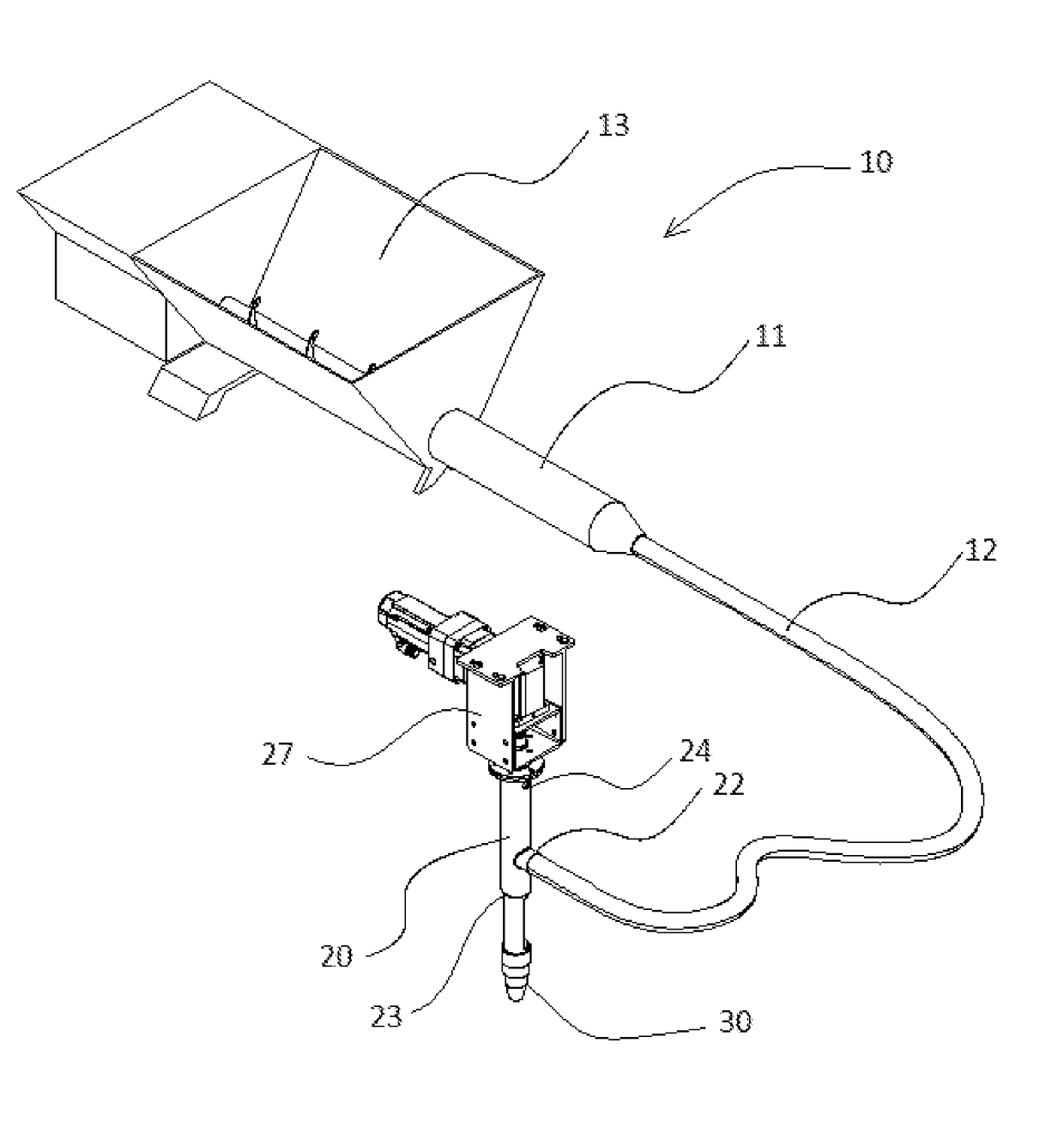
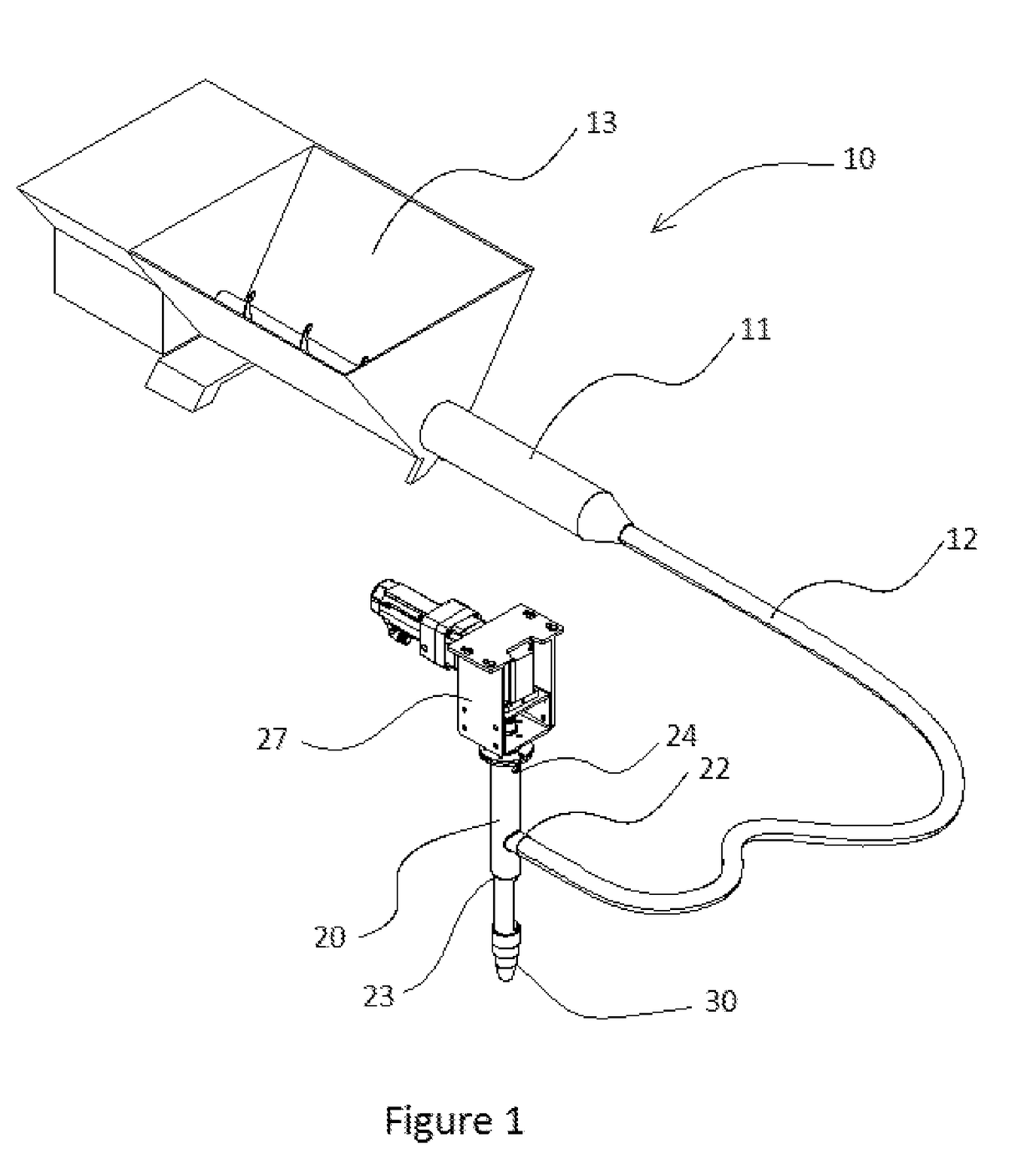
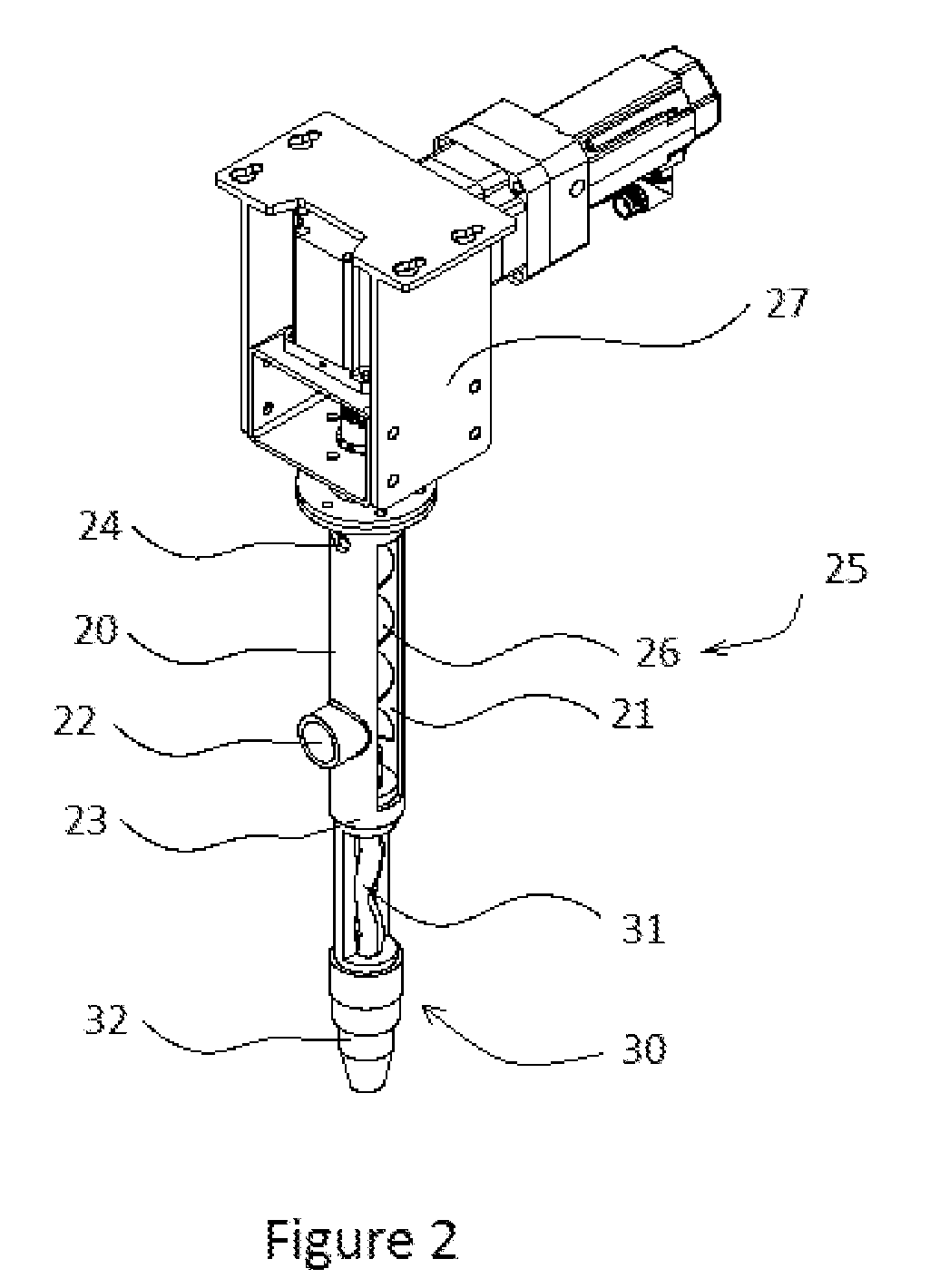
[0028]In accordance with a preferred embodiment, FIG. 1 to FIG. 4 depict the machine as a presently embodiment, wherein the machine comprises a slurry supply component 10, a buffer chamber 20, and a flow control dispenser 30.

[0029]Referring to FIG. 1, the slurry supply component 10 comprises a supply pump 11, a pipe 12, and a slurry tank 13. The supply pump 11 and the pipe 12 are connected to transport the slurry from the slurry tank 13 to the buffer chamber 20 which may be a distance away. The pipe 12 is soft and flexible; therefore the buffer chamber 20 and the flow control dispenser 30 can work in a remote position, and can be moved during working, at the same time the supply pump 11 position could be fixed.

[0030]Since the tank 13 and the supply pump 11 don't need to be moved during working, the tank 13 may have a large capacity, and is easy to refill. This makes it possible for the system to work continuously for a long time. In a preferred embodiment, the slurry material is con...


PUM

PropertyMeasurementUnit
Pressureaaaaaaaaaa
Flow rateaaaaaaaaaa
Volumeaaaaaaaaaa

Abstract

A slurry dispense system utilizes a buffer chamber to release the pressure from the supply pump, and buffer the irregular flow rate of the supply pump. It also utilizes a positive displacement pump to control the dispense flow. With the help of the buffer chamber, the positive displacement pump is able to provide a constant flow rate, and can be accurately controlled. A high resolution and a high speed can be achieved at the same time.

Description

BACKGROUND1. Field of the Invention[0001]The present invention relates to a slurry dispense system. More particularly, the system dispenses fluidic materials with accurate flow control and is adopted for concrete 3D printing.2. Discussion of the Related Art[0002]Construction industry is an ancient but still a promptly developing industry which keeps seeking new technologies to reduce the cost, increase the efficiency, and create new effects. 3D printing is one of these computer aided manufacturing techniques getting more and more attention. 3D printing has many advantages including quick production, less waste, high flexibility, accessibility, etc. which has great potential in construction manufacturing. The objects of 3D printing vary from a small vase to a whole castle.[0003]Three dimensional (3D) printing is also known as additive manufacturing. It is achieved by placing some special material layer by layer according to a particular 2D pattern. The placed material will solidify, ...

Claims


Application Information

Patent Timeline
IPC IPC(8): B28B1/00B28C5/16B28C5/12B28C5/08B28C7/16B01F7/24B01F15/02B33Y30/00B28B17/00B33Y50/02
CPCB28B1/001B28C5/16B28C5/1253B28C5/0818B28C7/161B28C7/163B01F2215/0047B01F7/248B01F15/0283B33Y30/00B28B17/0081B33Y50/02B01F7/246B28C7/167E04G2021/049E04G21/0427B01F27/9213B01F27/923B01F35/7544B01F2101/28
Inventor ZHANG, JING
Owner ZHANG JING
Why Eureka
Try Eureka