Eureka AIR delivers breakthrough ideas for toughest innovation challenges, trusted by R&D personnel around the world.

Fire containment system, devices and methods for same and for firefighting systems

a fire containment system and fire containment technology, applied in the field of fire containment systems, can solve the problems of indiscriminate water distribution, damage to other items or regions, and damage to items or regions that are already on fir

Inactive Publication Date: 2018-07-19
WERTSBERGER SHALOM
View PDF1 Cites 32 Cited by
  • Summary
  • Abstract
  • Description
  • Claims
  • Application Information

AI Technical Summary

Benefits of technology

The invention is a fire containment system for protecting a protected volume. It includes a controller, a fire suppressant distribution system, and a plurality of sensors. The controller is in communication with the fire suppressant distribution system and is capable of activating the system in response to fire detection by the sensors. The system uses a sprinkler and a plurality of ports to disperse fire suppressant in the protected volume. The sensors can detect fire events and communicate the information to the controller, which activates the appropriate ports to disperse fire suppressant. The system can be used in both dry and wet systems and can contain fire in the protected volume in multiple directions. The sensors can be a variety of types and can communicate with the controller through wired or wireless communication. The invention provides an effective and efficient solution for protecting firefighters and fireproofing buildings.

Problems solved by technology

At the root of such assumption is firstly the concept that an item or a region that is already on fire is likely damaged behind repair by the time it causes a sprinkler to trip.
At the same time, indiscriminant distribution of water may damage other items or regions that are not endangered if the fire of the first item is contained before the fire reaches those items and regions.
However such method is generally to be determined by the firefighters upon arriving at the scene and not automatic.

Method used


Image

  • Fire containment system, devices and methods for same and for firefighting systems
  • Fire containment system, devices and methods for same and for firefighting systems
  • Fire containment system, devices and methods for same and for firefighting systems

Examples


Embodiment Construction

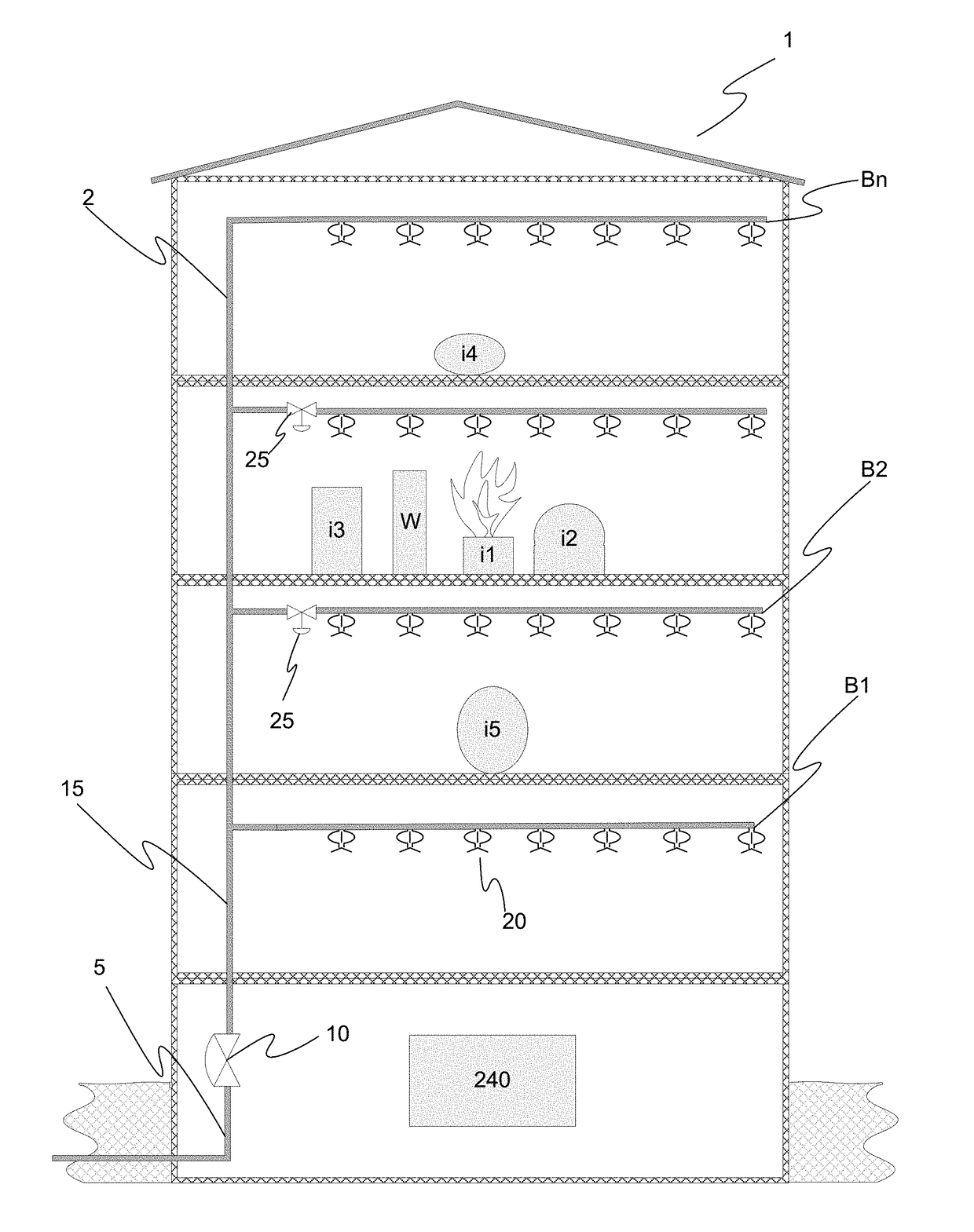
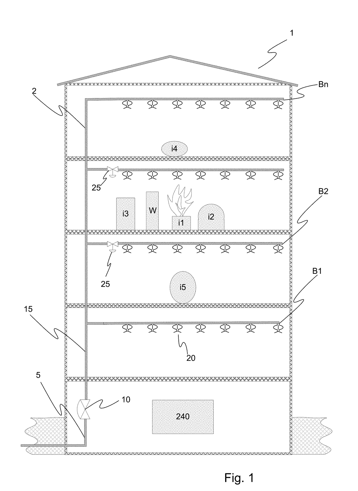
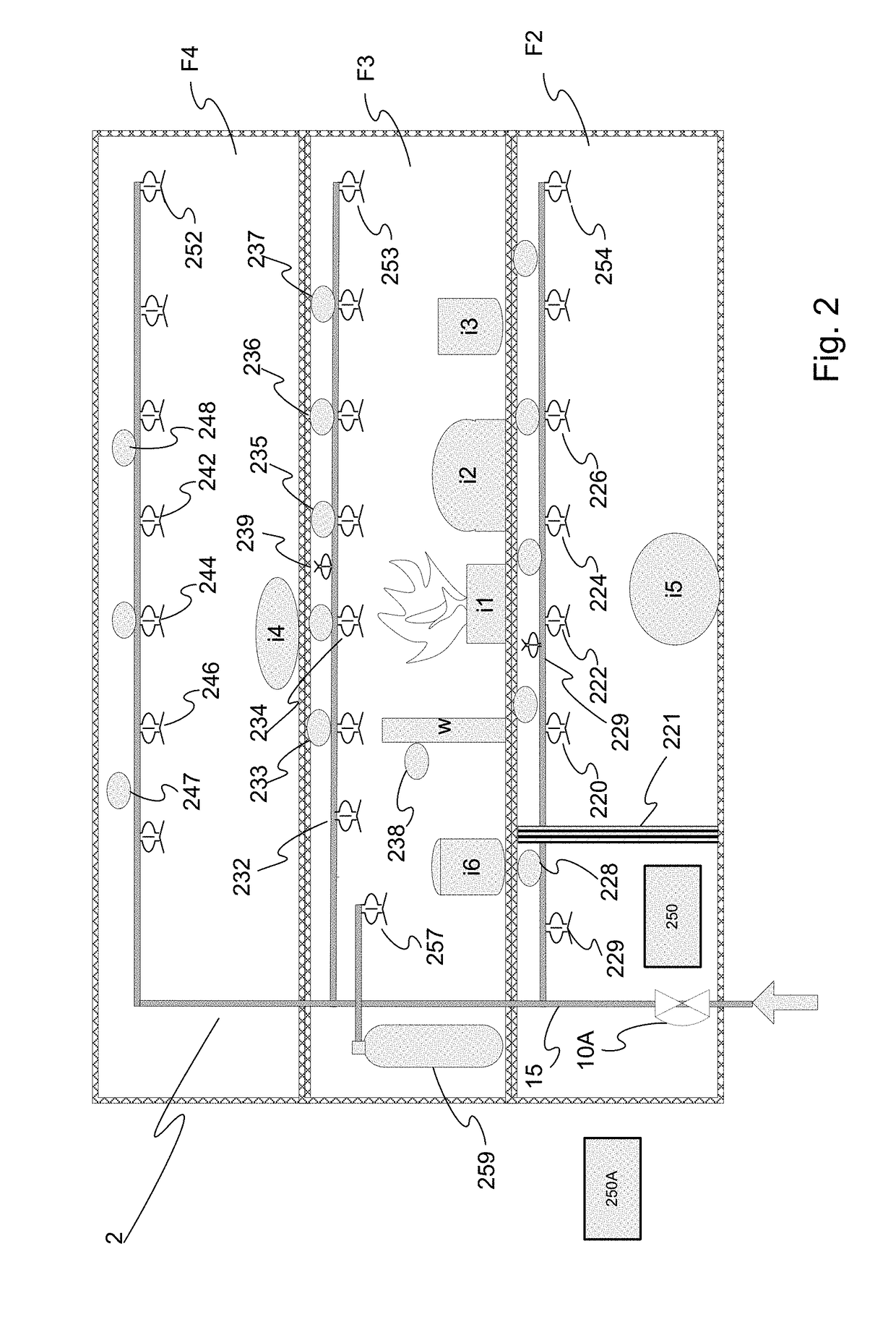
[0067]As explained above a basic principle of the fire containment system aspect of present invention revolves around containing the fire and an assumption is made that the region in which the fire started sustained a damage prior to the detection of the fire, and that while the source of the fire needs to be extinguished or otherwise handled, protecting the area surrounding the fire provides the best solution for minimizing fire damage. At the same time, the principle dictates that in most environment dispersing fire suppressant over the whole volume or significant portions thereof which are distal to the fire source causes unnecessary damage while oftentimes not contributing significantly to safety or to minimizing damage, and not even to extinguishing the fire. Furthermore indiscriminate fire suppressant distribution may reduce the supply of such suppressant from the area it is most needed. Notably, the fire must be monitored, and if it continues to expand, the expanded area must...


PUM


Abstract

An automatic fire containment system is disclosed, together with certain components which may be used therewith. An embodiment of the system attempts to provide fire suppressant to regions surrounding a fire zone, thus containing the fire within limited area, but not flooding a larger area than necessary to contain the fire. Sprinklers which may be selectively automatically activated electrically, optionally in addition to common heat triggering, are also provided. Sensors may be embedded in the sprinklers. Further provided are sprinkler capable of reporting activation thereof via electrical state change. Further provided are devices to reduce installation costs and increase the resolution of firefighting and / or fire containment systems by providing wireless communications between network nodes such as flow switches, valve status switch, and individual sensors, sprinkler, and other ports, and a control panel / controller.

Description

RELATED APPLICATIONS[0001]This application claims the benefit of priority of U.S. Provisional Patent Application No. 62 / 446,833, filed Jan. 16, 2017. This application is incorporated herein by reference in its entirety.FIELD OF THE INVENTION[0002]Aspects of this invention is generally directed to firefighting systems, and more particularly to fire containment systems providing control of various elements of the fire suppressant distribution system to contain fires and limit damage caused thereby, as well as to sprinklers and control equipment utilized in firefighting and / or fire containment systems.BACKGROUND OF THE INVENTION[0003]Firefighting systems, especially such that utilize sprinklers are common. In most sprinkler systems the fire suppressant is water, and for brevity, these specifications would use the water as equivalent to any fire suppressant. Sprinkler systems distribute fire suppressants via a distribution system in response to a sprinkler activation which commonly resu...

Claims


Application Information

Patent Timeline
Patent Type & Authority Applications(United States)
IPC IPC(8): A62C37/40A62C37/36A62C37/46G08B17/02
CPCA62C37/40A62C37/04A62C37/46G08B17/02A62C37/44G08B17/04G08B17/06
Inventor WERTSBERGER, SHALOM
Owner WERTSBERGER SHALOM
Why Eureka
Eureka Blog
Learn More