Security lock for removably suspended electronically addressable object and system

a technology of electronic addressable objects and security locks, which is applied in the field of collection object management systems, can solve the problems of requiring a complex object management system, affecting so as to ensure the integrity of the collection of objects and enhance the security of the system

Active Publication Date: 2018-07-05
IMICRODATA
View PDF0 Cites 4 Cited by
  • Summary
  • Abstract
  • Description
  • Claims
  • Application Information

AI Technical Summary

Benefits of technology

The invention is a system that improves security and prevents unauthorized removal of objects. It uses Bluetooth technology to locate lost or missing objects. The locking feature ensures that the object carrier is securely locked in place, while the Bluetooth feature allows for easy remote tracking of the object. Overall, this system provides better security and management for objects.

Problems solved by technology

In supermarkets, a collection of a large number of different types of items, such as meats, produce, canned goods and the like is usually in inventory, with the number and types of objects varying widely on a daily basis and thus requiring a complex objects management system.
While the '010 system greatly improves management of the removably suspended objects registered in the system, the integrity of the collection of objects is susceptible to unauthorized removal of the object carriers from the suspension members.
This compromised integrity of the collection of objects is less than desirable.

Method used


Image

  • Security lock for removably suspended electronically addressable object and system
  • Security lock for removably suspended electronically addressable object and system
  • Security lock for removably suspended electronically addressable object and system

Examples


Embodiment Construction

[0030]The invention has wide application to a large variety of electronically addressable removably retained objects. The following is a detailed description of one application of the invention to removably retained objects which are keys attached to object carriers which function as key holders.

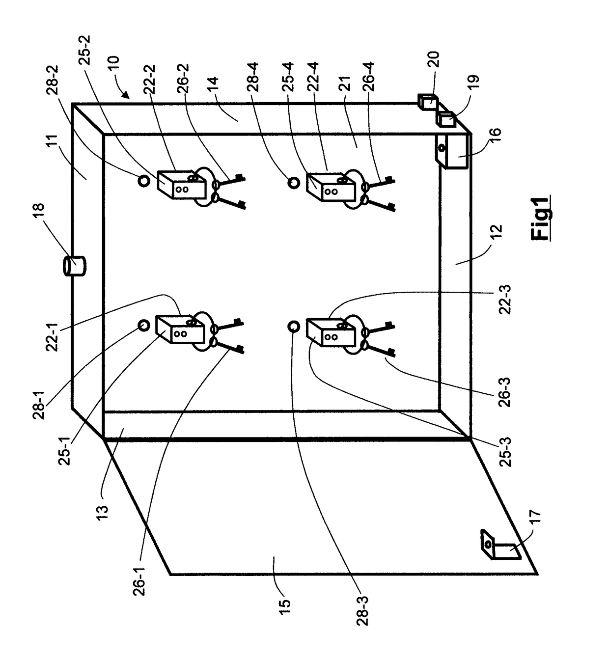
[0031]Turning now to the drawings, FIG. 1 is a perspective view of a cabinet for storing several removably retained objects each in the form of a key and a key holder object carrier. As seen in this Fig., a cabinet generally designated with reference numeral 10 has a top wall 11, a bottom wall 12, a left side wall 13, a right side wall 14 and a hinged door 15. Door 15 may be fabricated from a transparent material, such a transparent plastic or tempered glass so that the interior contents are visible from outside the cabinet 10 when door 15 is closed. A conventional electrically operable lock mechanism 16 is attached to the interior of cabinet 10 and a catch 17 operable with lock mechanism 16...


PUM


Abstract

An electronically addressable object carrier for enabling the management of removably suspended objects, such as keys, distributed in an object location space, The object carrier includes a housing having an object retention element for securing an object to the object carrier and a lock element for releasable engagement with an associated locking device, the microcontroller having a unique object address serving to identify an object secured to the object carrier; a plurality of electrically conductive contact pads in the housing for electrically coupling the microcontroller to a source of object address signals and electrical power signals and a visible indicator coupled to the microcontroller for activation whenever the microcontroller receives an address signal representative of the unique object address. The lock element is a recess formed in a surface of the housing with an abutment edge. The associated locking device is a solenoid having a retractable plunger terminating in a control element which engages the recess. The locking device is mounted adjacent a mounting aperture in a support element, such as a cabinet interior wall. In use, the carrier is inserted into the wall aperture until the control element engages the housing recess, which locks the carrier in place. To unlock, the solenoid is operated to retract the plunger to release the carrier for manual removal.

Description

BACKGROUND OF THE INVENTION[0001]This invention relates to collective objects management systems in general, and in particular to an improved collective objects management system using object identification with digital addresses. More particularly, this invention relates to an improvement for a collective objects management system using object identification with digital addresses, the improvement pertaining to security locks for removably suspended object carriers.[0002]The term “collective objects management systems” is a term coined to denote systems for generally keeping track of items (“objects”) in a collection of items. For example, an automobile parts warehouse at any given time has a collection of vehicle parts (“objects”) in inventory. The kind and number of such parts varies every day, as parts are sold and new parts are received. In order to keep track of the number and kind of vehicle parts in inventory, some type of collective vehicle parts management system must be u...

Claims


Application Information

Patent Timeline
Patent Type & Authority Applications(United States)
IPC IPC(8): G07C9/00G08B5/36E05B47/00E05B47/06E05B41/00E05B73/00E05B65/00E05B17/10
CPCG07C9/00111G07C9/00119G07C9/00309G07C9/00896G08B5/36G07C9/00571G07C2009/00539E05B47/06E05B41/00E05B73/0005E05B65/0075E05B17/10E05B47/0001A47G29/10E05B19/0005G06Q10/0875E05B47/0004G08B13/1427G08B13/2462G08B21/24G07C2009/00936G07C9/00912G07C9/00817G07C2009/00769G07C9/28G07C9/29
Inventor ZHU, SHENGBOHUANG, SU SHIONG
Owner IMICRODATA
Why Eureka
Try Eureka