Thermoelectric Devices

a technology of thermoelectric devices and thermoelectric devices, which is applied in the field of additive manufacturing, can solve the problems of reducing reliability and reproducibility, degrading the performance of useful devices, and costing and complexity of assembling useful devices which incorporate, so as to achieve greater manufacturing speed and reduce manufacturing costs

Active Publication Date: 2018-06-07
XILICO LLC
View PDF5 Cites 2 Cited by
  • Summary
  • Abstract
  • Description
  • Claims
  • Application Information

AI Technical Summary

Benefits of technology

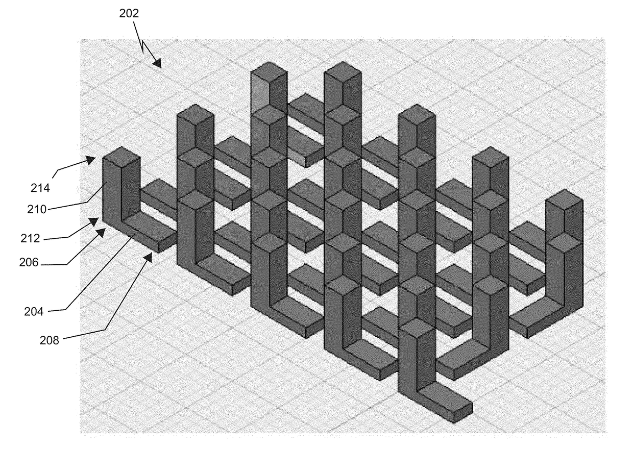
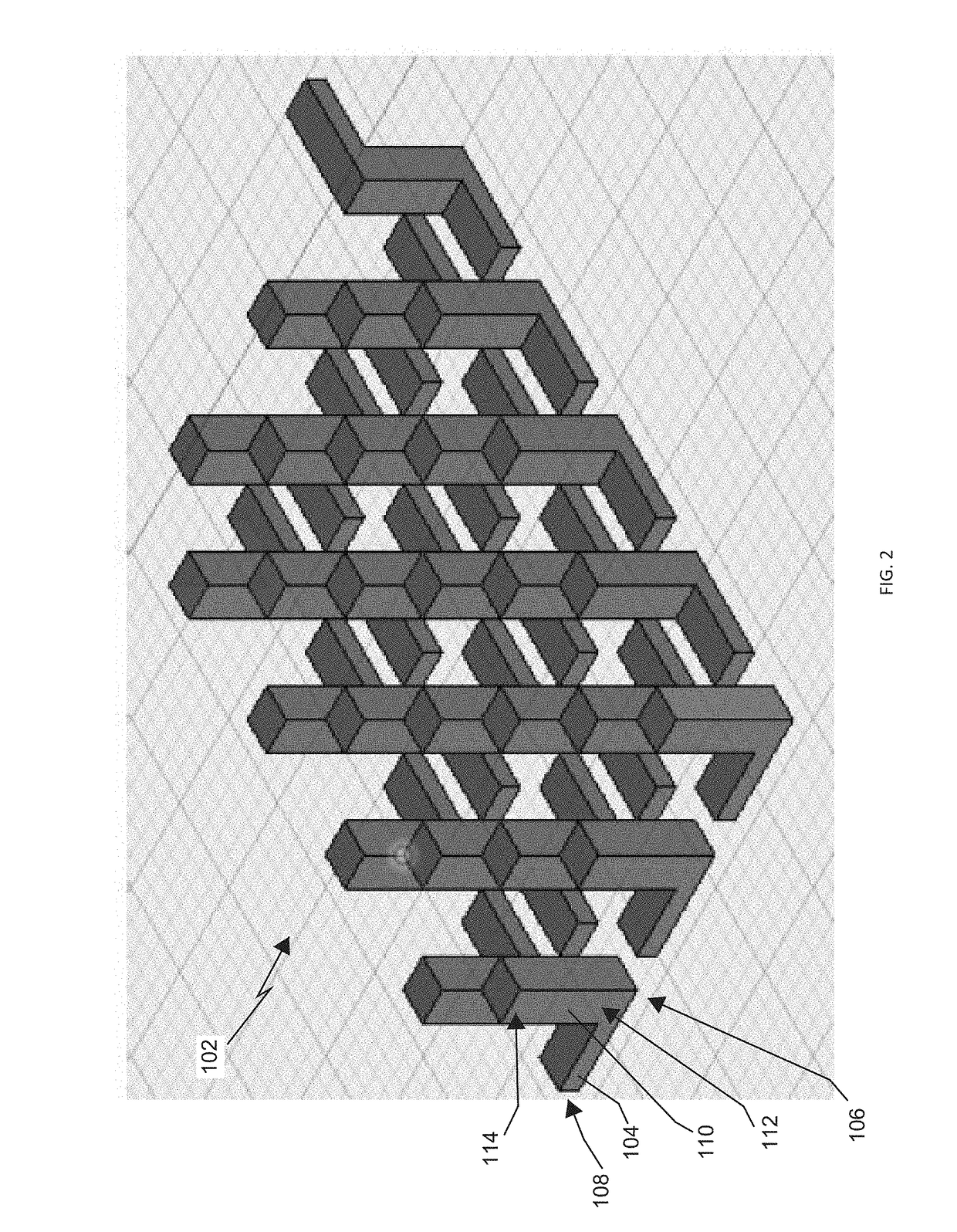
The present patent describes a solution for the challenges of designing and manufacturing thermoelectric generators by redesigning the thermoelectric generator and increasing its symmetry to allow for fewer parts and a simpler 3-D printing process. Additionally, the use of interconnect pieces from the same material as the legs provides improved electrical conductivity and reduces contact resistance, resulting in improved device performance. The orientation of the 3-D printing process can also be adjusted to optimize the properties of the final components. The simplicity of the components allows for faster and less expensive manufacturing.

Problems solved by technology

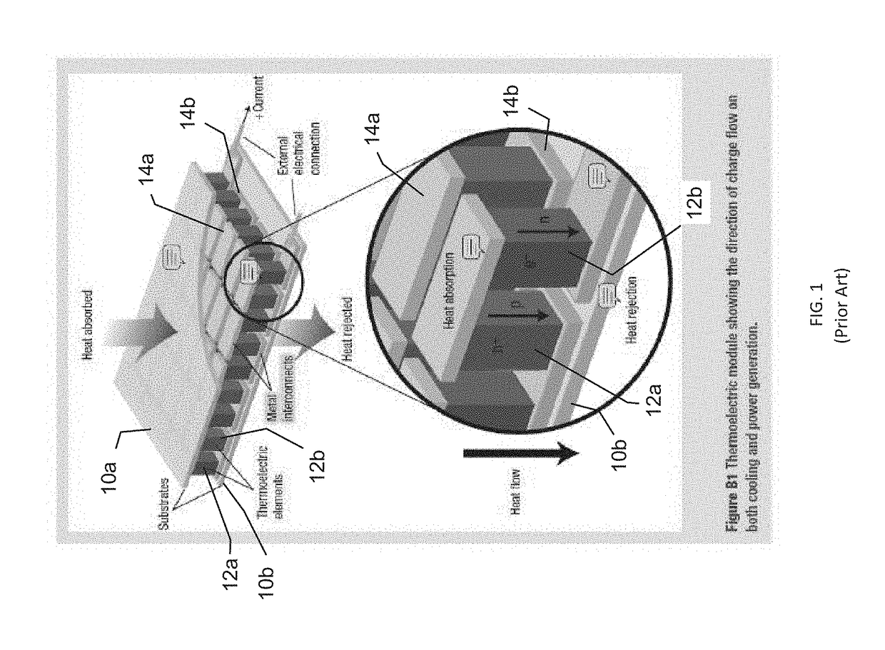
In addition to the challenge of developing efficient and cost-effective thermoelectric materials, another impediment to the widespread applicability of thermoelectric generators is the cost and complexity of assembling useful devices which incorporate them.
Most such devices are currently assembled by hand using a variety of different materials, which not only makes them cost-prohibitive but also introduces unnecessary complication, lowers reliability and reproducibility, and degrades their performance.
Although additive manufacturing would appear to provide an excellent process for both prototyping and manufacturing thermoelectric generators, three major impediments have thus far hindered this approach.
First, thermoelectric generators are generally constructed from a heterogeneous set of materials, including polymers, carbon forms, metals, plastics, and other materials, which generally cannot be 3-D printed using any one 3-D printer.
Thus, the assembly of thermoelectric generators has been restricted to manual methods.
The other impediment has been that it has not been possible to 3-D print the types of thermally- and electrically-conducting materials which are required for the construction of efficient thermoelectric generators.
Such materials have demanding properties which require very specific operational parameters, and have thus far proven impossible to 3-D print.
A drawback of SLA, however, is that it is generally restricted to a single material.
This method of fabrication can lead to even greater manufacturing speeds and lowered manufacturing costs.

Method used


Image

  • Thermoelectric Devices
  • Thermoelectric Devices
  • Thermoelectric Devices

Examples


example 1

[0039]In one embodiment, a sheet of the non-conducting polyimide Kapton® substrate 100 of the appropriate thickness was affixed to the build plate of a commercial stereolithographic printer (Ember from Autodesk, San Francisco, Calif.). An electrically-conducting photopolymer resin was prepared by mixing together about 65% to about 75% of Photomer 4050 (PEG 200 diacrylate, IGM Resins, St. Charles, Ill.), about 15% to about 25% of SR494 from Sartomer Americas (ethoxylated pentaerythritol tetraacrylate, Exton, Pa.), about 2.0 weight % of BAPO (phenylbis(2,4,6-trimethylbenzoyl)phosphine oxide), IGM Resins, Charlotte, N.C.), and about 40 mg of single-walled carbon nanotubes (SWCNT) obtained from OCSiAl (Palo Alto, Calif.), and doped with p-type material to obtain about 50 mL of an electrically-conducting p-type photocurable resin. Preferably, Photomer 4050 is about 73% of the total resin. The resin was dispersed by power sonication with a Branson (Danbury, Conn.) Digital Sonifier model 2...

example 2

[0042]In another embodiment, a prototype thermoelectric generator was fabricated by first preparing an electrically non-conducting acrylate resin by mixing together about 65% to about 75% of Photomer 4050 (PEG 200 diacrylate, IGM Resins, St. Charles, Ill.), about 15% to about 25% of SR494 from Sartomer Americas (ethoxylated pentaerythritol tetraacrylate, Exton, Pa.), about 2.0 weight % of BAPO (phenylbis(2,4,6-trimethylbenzoyl)phosphine oxide), IGM Resins, Charlotte, N.C.), and agitated for 24 hours using a magnetic stirrer to obtain about 50 mL of resin. Preferably, the Photomer is about 73% of the total resin. The non-conducting substrate layer 100 of an arbitrary size was printed onto the build plate of a commercial stereolithographic printer (Ember from Autodesk, San Francisco, Calif.). An electrically-conducting photopolymer resin was prepared by mixing together about 65% to about 750% of Photomer 4050 (PEG 200 diacrylate, IGM Resins, St. Charles, Ill.), about 15% to about 25% ...

example 3

[0044]In another embodiment, a prototype thermoelectric generator was fabricated by first preparing an electrically non-conducting photopolymer resin by mixing together about 65% to about 75% of Photomer 4050 (PEG 200 diacrylate, IGM Resins, St. Charles, Ill.), about 15% to about 25% of SR494 from Sartomer Americas (ethoxylated pentaerythritol tetraacrylate, Exton, Pa.), about 2.0 weight % of BAPO (phenylbis(2,4,6-trimethylbenzoyl)phosphine oxide), IGM Resins, Charlotte, N.C.), and agitated for 24 hours using a magnetic stirrer to obtain about 50 mL of resin. Preferably, the Photomer was about 73% of the total resin. The non-conducting substrate layer 100 of an arbitrary size was printed onto the build plate of a commercial stereolithographic printer (Ember from Autodesk, San Francisco, Calif.). An electrically-conducting photopolymer resin was prepared by mixing together about 65% to about 750% of Photomer 4050 (PEG 200 diacrylate, IGM Resins, St. Charles, Ill.), about 15% to about...


PUM

PropertyMeasurementUnit
heightsaaaaaaaaaa
heightsaaaaaaaaaa
heightsaaaaaaaaaa

Abstract

This disclosure relates to methods for manufacturing devices capable of functioning as thermoelectric generators and related objects by the process of additive manufacturing or by 3-D printing or by casting. This disclosure also particularly relates to the uses of the thermoelectric generators and related objects produced by these methods.

Description

CROSS-REFERENCE TO RELATED APPLICATION[0001]This patent application is a continuation of U.S. patent application Ser. No. 15 / 181,298, filed Jun. 13, 2016, which claims the benefit of U.S. Provisional Patent Application Ser. No. 62 / 174,968, entitled “Thermoelectric Devices,” filed Jun. 12, 2015, which applications are incorporated in their entirety here by this reference.BACKGROUNDTechnical Field[0002]This disclosure relates to the field of additive manufacturing. This disclosure also relates to the field of 3-D printing. This disclosure particularly relates to the fabrication of thermoelectric devices, such as thermoelectric generators. This disclosure also relates to methods for employing additive-manufacturing systems and / or devices for producing useful materials and / or objects, including thermoelectric devices, such as thermoelectric generators.Description of Related Art[0003]There is currently considerable research and development effort being directed at the development of devi...

Claims


Application Information

Patent Timeline
Patent Type & Authority Applications(United States)
IPC IPC(8): H01L35/34H01L35/32
CPCH01L35/32H01L35/34B33Y80/00B33Y10/00H10N10/01H10N10/17
Inventor CAUCHON, GREG P.MCFADDEN, IAN D.SACHDEV, SAMIR
Owner XILICO LLC
Why Eureka
Try Eureka