Ion exchanger

a technology of ion exchanger and cation exchanger, which is applied in the direction of cation exchanger materials, electrochemical generators, separation processes, etc., can solve the problems of increasing the load of the pump that circulates the coolant, affecting the efficiency of the fuel cell, and causing the leakage of electric energy to the outside of the fuel cell through the coolant, so as to reduce the size of the ion exchanger and shorten the length of the communication tube. ,

Active Publication Date: 2018-05-24
TOYODA GOSEI CO LTD
View PDF3 Cites 4 Cited by
  • Summary
  • Abstract
  • Description
  • Claims
  • Application Information

AI Technical Summary

Benefits of technology

[0011]The invention has been made in consideration of the above-described circumstance, and an object thereof is to provide an ion exchanger which can change ion exchange efficiency or a pressure loss while suppressing complexity and enlargement of a structure in a cooling system of a fuel cell system.

Problems solved by technology

As a result, there is a concern that electric leakage to the outside from the fuel cell through the coolant is caused.
Furthermore, there is also a concern that a generating efficiency of the fuel cell deteriorates.
When the pressure loss increases, a load of a pump that circulates the coolant also increases.
Accordingly, power consumption due to the pump increases, and there is a concern that the generating efficiency of the fuel cell deteriorates.
However, in an initial operation stage of the fuel cell system, since a large number of ions are eluted from a configuration component, such as a pipe, which has just been assembled, an ion elution amount in the cooling system becomes extremely large.
However, in the configuration described in JP-A-2010-198796, it is necessary to provide a plurality of flow paths that store the ion exchange resin therein, or a mechanism which switches the flow paths in accordance with the flow velocity of the coolant, and there is a concern that the size of the ion exchanger increases and the structure thereof becomes complicated.
In the ion exchanger of the related art, since a configuration in which the entire amount of introduced coolant passes through the ion exchange resin portion is employed, the pressure loss is extremely large.
However, in a case where the bypass flow path is curved in a U shape or in a clamp shape, there is a concern that the pressure loss naturally increases.
In addition, in a case where the bypass flow path which bypasses the ion exchange resin portion is provided in the case portion, there is a concern that the size of the ion exchanger increases.

Method used


Image

  • Ion exchanger
  • Ion exchanger
  • Ion exchanger

Examples


first embodiment

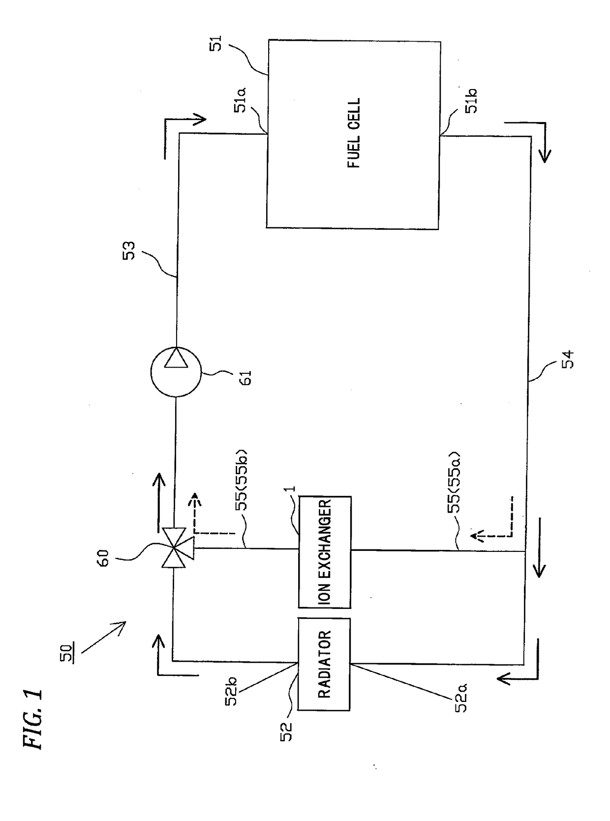
[0054]Hereinafter, one embodiment of the invention will be described with reference to the drawings. An ion exchanger according to the invention is, for example, used in a cooling system of a fuel cell system in a fuel cell vehicle. FIG. 1 is a schematic configuration view illustrating a cooling system 50 of the fuel cell system to which an ion exchanger 1 which will be described later is attached.

[0055]As illustrated in FIG. 1, in the cooling system 50, the flow path in which the coolant circulates is mainly configured of an upstream side pipe 53 which connects an inlet port 51a of a fuel cell 51 and an outlet port 52b of a radiator 52 to each other, a downstream side pipe 54 which connects an outlet port 51b of the fuel cell 51 and an inlet port 52a of the radiator 52 to each other, and a bypass pipe 55 connected to the radiator 52, the upstream side pipe 53, and the downstream side pipe 54 in parallel.

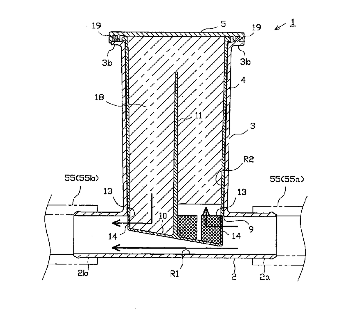
[0056]The ion exchanger 1 is installed in the bypass pipe 55, and a three-way v...

second embodiment

[0096]Next, a second embodiment will be described in detail with reference to FIGS. 6 and 7. FIG. 6 is a sectional view illustrating the ion exchanger in the first assembled state according to the embodiment, and FIG. 7 is a sectional view illustrating the ion exchanger in the second assembled state. However, the parts that overlap those in the above-described first embodiment will be given the same reference names and the same reference numbers, the detailed description thereof will be omitted, and the description will focus on parts different from those of the first embodiment hereinafter.

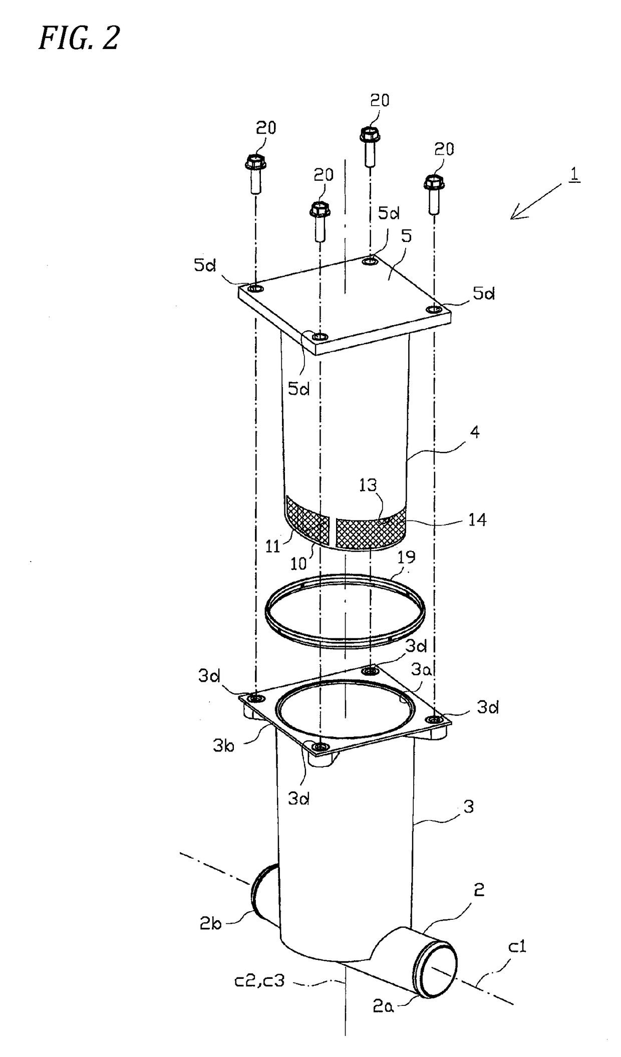
[0097]In the embodiment, in addition to the circumferential wall portion of the inner cylinder portion 4, the opening portion 13 is also formed in the bottom wall portion 10, and the mesh 14 is attached thereto. In addition, in the first assembled state (refer to FIG. 6), the inner cylinder portion 4 is stored such that the lowest part of the bottom wall portion 10 is positioned on the most upstr...

third embodiment

[0102]Next, a third embodiment will be described in detail with reference to FIGS. 8 and 9. FIG. 8 is a sectional view illustrating the ion exchanger in the first assembled state according to the embodiment, and FIG. 9 is a sectional view illustrating the ion exchanger in the second assembled state. However, the parts that overlap those in the above-described first embodiment will be given the same reference names and the same reference numbers, the detailed description thereof will be omitted, and the description will focus on parts different from those of the first embodiment hereinafter.

[0103]In the inner cylinder portion 4, two partition wall portions 11A and 11B are formed to divide the inside into four areas. The partition wall portions 11A and 11B are formed to intersect with each other in a cross-sectional shape in the center axial line C3. In addition, in the first assembled state (refer to FIG. 8), a state is achieved where the partition wall portion 11A is disposed along ...


PUM

PropertyMeasurementUnit
temperatureaaaaaaaaaa
areaaaaaaaaaaa
temperatureaaaaaaaaaa

Abstract

An ion exchanger used in a cooling system of a fuel cell system, includes: a communicating tube portion including a first flow path which allows coolant introduced from one side to pass therethrough to the other side; a case portion which is provided to communicate with the communicating tube portion; and a storage body which is assembled to the case portion, has a second flow path in which a part of the coolant branches and flows from the communicating tube portion, and is merged with the communicating tube portion again, and stores an ion exchange resin in the second flow path, wherein: an assembled state of the storage body with respect to the case portion is changeable into a plurality of kinds; and a proportion of the coolant that flows to the second flow path is changeable by changing the assembled state of the storage body.

Description

CROSS-REFERENCE TO RELATED APPLICATION(S)[0001]This application is based upon and claims the benefit of priority from Japanese Patent Application No. 2016-226638, filed on Nov. 22, 2016, the entire contents of which are incorporated herein by reference.BACKGROUND1. Field of the Invention The present invention relates to an ion exchanger used in a cooling system of a fuel cell system.2. Description of the Related Art[0002]In a fuel cell system, when hydrogen and oxygen chemically react to each other in a fuel cell and power generation is performed, the fuel cell generates heat. Therefore, in the fuel cell system, a cooling system is provided which maintains the fuel cell to be at an appropriate temperature during the power generation by circulating coolant.[0003]In the cooling system, when ion concentration in the coolant increases by acid production caused by thermal deterioration of coolant or elution of ions from a pipe component or the like, conductivity of the coolant increases....

Claims


Application Information

Patent Timeline
Patent Type & Authority Applications(United States)
IPC IPC(8): H01M8/04044B01D15/36B01D15/14H01M8/04029
CPCH01M8/04044B01D15/362B01D15/363B01D15/14H01M8/04029H01M2008/1095H01M2250/20Y02T90/40Y02E60/50
Inventor YAMAGUCHI, NAOKIKUSABA, KOSUKEOJIO, TATSUYA
Owner TOYODA GOSEI CO LTD
Why Eureka
Try Eureka