Inverter device of rotating electrical machine, and driving method for rotating electrical machine

a technology of electrical machines and inverters, which is applied in the direction of electric generator control, dynamo-electric converter control, dynamo-electric gear control, etc., can solve the problems of complex control, inability to execute synchronous pwm control when, and reduce switching loss, suppressing control complexity

Inactive Publication Date: 2014-10-07
TOYOTA IND CORP
View PDF20 Cites 2 Cited by
  • Summary
  • Abstract
  • Description
  • Claims
  • Application Information

AI Technical Summary

Benefits of technology

[0009]The present invention aims at providing an inverter device of a rotating electrical machine capable of reducing a switching loss while suppressing the complexity of control.

Problems solved by technology

Therefore, complicated control is performed.
In addition, since the frequency of an output waveform is to be fixed, the synchronous PWM control cannot be executed when the frequency is variable.

Method used


Image

  • Inverter device of rotating electrical machine, and driving method for rotating electrical machine
  • Inverter device of rotating electrical machine, and driving method for rotating electrical machine
  • Inverter device of rotating electrical machine, and driving method for rotating electrical machine

Examples


Embodiment Construction

[0017]The embodiment of the present invention is described below with reference to the attached drawings.

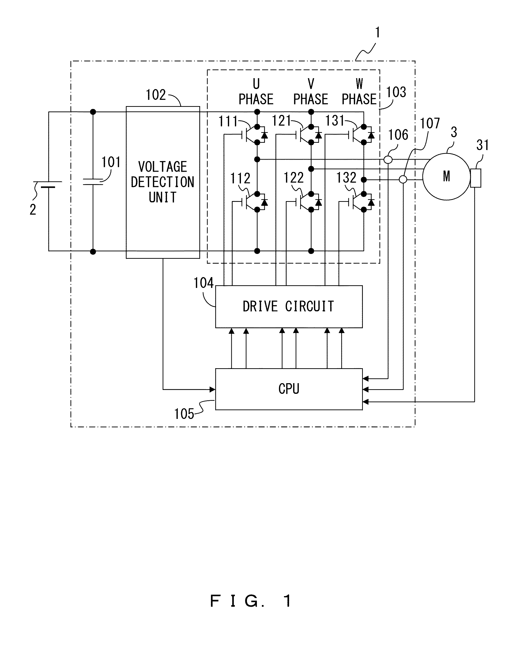
[0018]FIG. 1 is an explanatory view of the configuration of the inverter device of a rotating electrical machine according to the present embodiment.

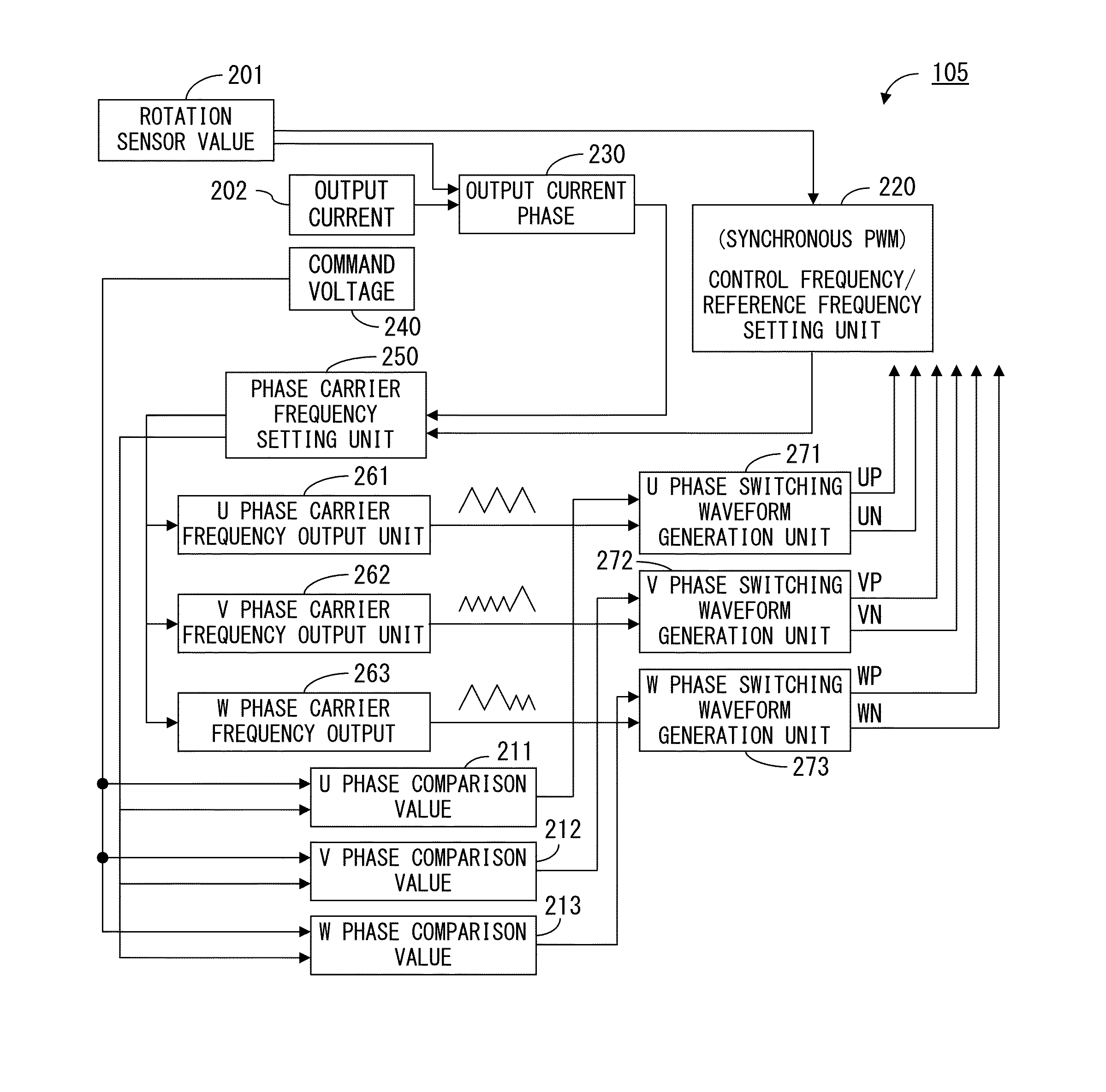
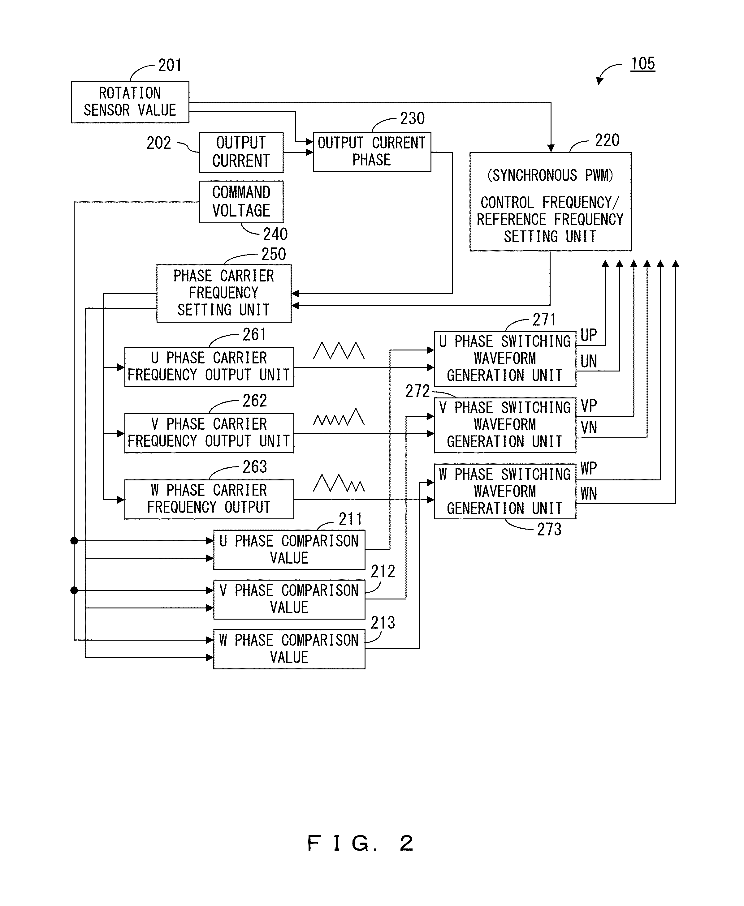
[0019]An inverter device 1 of the rotating electrical machine (hereafter referred to as an “inverter device”) drives a motor 3 as a rotating electrical machine using the voltage applied from a DC power supply 2. As illustrated in FIG. 1, the inverter device 1 includes a capacitor 101 connected in parallel to the DC power supply 2, a voltage detection unit 102 for detecting the voltage between the both ends of the capacitor 101, an inverter circuit 103 for which, for example, an n-channel IGBT (insulated gate bipolar transistor) is prepared as two switching elements for each phase, a drive circuit 104 for generating and outputting a drive signal of each IGBT of the inverter circuit 103, a CPU 105 for controlling the generation of driv...


PUM


Abstract

An inverter device of a rotating electrical machine drives a multiphase rotating electrical machine having the variable number of rotations using a switching element provided for each phase. An example of the inverter device of the rotating electrical machine includes: a frequency setting unit for determining and setting a carrier frequency of a carrier signal for use in driving the switching element for each phase depending on the state of each phase of the rotating electrical machine for each specified electrical angle obtained by equally dividing a cycle of an electrical angle; and a signal generation unit for generating a drive signal for drive of the switching element of each phase using the carrier signal of the carrier frequency set for each phase by the frequency setting unit. The carrier frequency of each phase is an integral multiple of the phase voltage frequency at the specified electrical angle.

Description

BACKGROUND OF THE INVENTION[0001]1. Field of the Invention[0002]The present invention relates to the technology of driving a rotating electrical machine by supplying a current for each phase.[0003]2. Description of the Related Art[0004]Normally, an inverter device is used in driving a rotating electrical machine such as a 3-phase motor. The inverter device is normally provided with two switching elements for each phase (a total of 6 elements). Thus, the inverter device controls the driving voltages of three phases by driving on and off the six switching elements, thereby generating a rotating magnetic field for the rotating electrical machine. The inverter device of the rotating electrical machine is to drive the rotating electrical machine using the switching elements.[0005]As a method for controlling the level of the voltage to be applied to a rotating electrical machine and the frequency, PWM control drives on and off the switching element for each phase, and applies a voltage of...

Claims


Application Information

Patent Timeline
Patent Type & Authority Patents(United States)
IPC IPC(8): H02P23/00H02M7/48H02P21/22H02P27/06H02P27/08
CPCH02P27/04
Inventor TAKANO, RYUJIYAMADA, YOHEIOHBA, TOMOHIROIKEDA, SHIGEKI
Owner TOYOTA IND CORP
Why Eureka
Try Eureka