Demultiplexing method and device

a multi-layer and multi-layer technology, applied in the field of demultiplexing methods and devices, can solve the problems of inability to synchronize leds, inability to deliver the desired sub-meter or even centimeter accuracy, and difficulty in accurate indoor positioning

Active Publication Date: 2018-05-24
KATHOLIEKE UNIV LEUVEN
View PDF0 Cites 0 Cited by
  • Summary
  • Abstract
  • Description
  • Claims
  • Application Information

AI Technical Summary

Benefits of technology

[0005]It is an object of the present invention to provide a good system and method for demultiplexing signals.
[0006]It is an advantage of embodiments of the present invention to provide a good system and method for demultiplexing rectangular shaped signals from non-synchronized sources. More specifically it provides good systems and methods for demultiplexing signals from non-synchronized power switched intensity sources.
[0007]It is an advantage of embodiments of the present invention that use can be made of unsynchronized low bandwidth transmitters, leading to an easy implementation using for example current high efficiency LED drivers.

Problems solved by technology

The problem of accurate indoor positioning is still an open challenge.
Indoors however, GPS does not deliver the desired sub-meter or even centimeter accuracy due to fading effects.
The LEDs are, in general, not part of a communication network, with the consequence that there is no synchronization possible between the LEDs with the contemporary topology.
In U.S. Pat. No. 3,575,665 the higher harmonics are used to filter out the false pulses, consequently it does not provide a demultiplexing method and / or device.

Method used


Image

  • Demultiplexing method and device
  • Demultiplexing method and device
  • Demultiplexing method and device

Examples


example

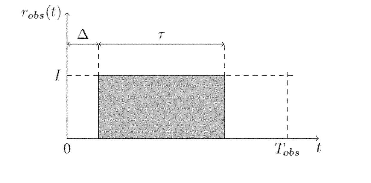
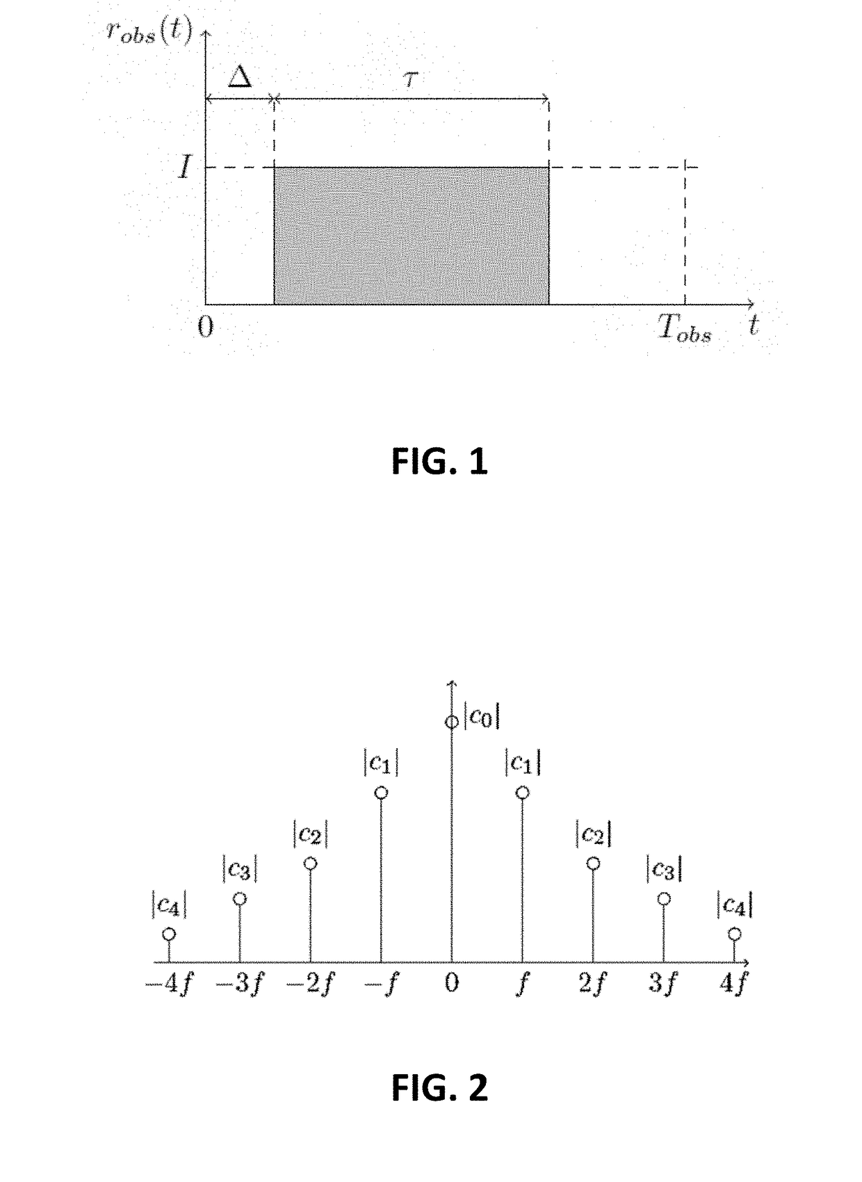
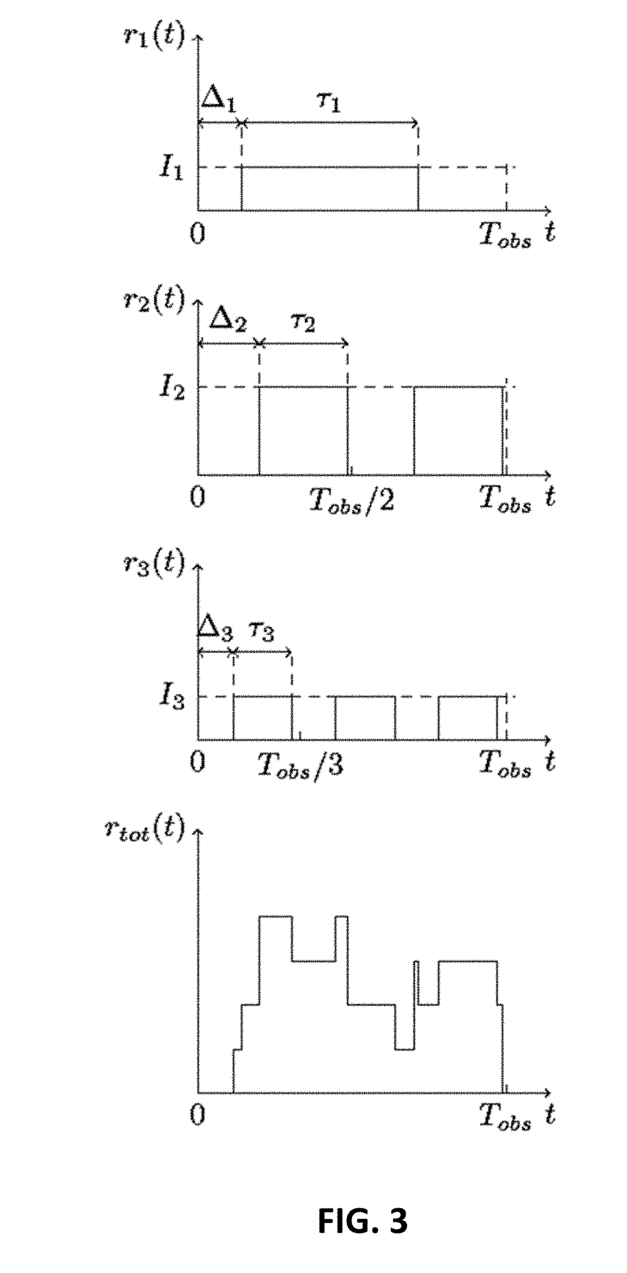
[0061]By way of illustration, embodiments of the present invention not being limited thereto, a theoretical discussion as well as a practical example of a method and system according to an embodiment of the present invention is discussed below. It is to be noticed that the example given below is only one example of an embodiment of the present invention illustrating a possible implementation, but that embodiments of the present invention are not restricted thereto. It further is to be noticed that the symbols used in the equations given for illustrating the example below, do not necessarily have the same meaning as the symbols used in the equations shown when describing the detailed embodiments indicated above. The equations in the description below therefore should be seen as a separate set of equations.

[0062]In the example, a technique is proposed that uses square waves and an FDMA scheme to build a solution where only the current lighting needs to be replaced with intelligent lig...


PUM


Abstract

A method is disclosed for demultiplexing a signal. The method comprises receiving the signal being a sum of at least two sub-signals, whereby each sub-signal comprises a different repetitive pattern. The method also comprises sampling the signal during a time period, whereby the time period is such that the different repetitive patterns of each sub-signal occur at least once and whereby at least sub-signals are periodic during with a different specific frequency. The method further comprises periodically expanding the signal in a Fourier series and obtaining the different complex spectral components of the periodically expanded signal.

Description

FIELD OF THE INVENTION[0001]The present invention relates to a demultiplexing method and device, in particular a method and device for demultiplexing signals, whereby the signals are a sum of at least two sub-signals, whereby each sub-signal comprises a different specific frequency. In further embodiments the present invention relates to a demultiplexing method and device for non-synchronized power switched keyed intensity sources.BACKGROUND OF THE INVENTION[0002]The problem of accurate indoor positioning is still an open challenge. For outdoor environments, the well-known Global Positioning System (GPS) is providing the solution. Indoors however, GPS does not deliver the desired sub-meter or even centimeter accuracy due to fading effects. For indoor environments, an accurate, wireless technology can enable location-based services (LBS). These services are e.g., indoor navigation, content delivery based on the position of the mobile node, heat mapping, path optimization, . . . . Num...

Claims


Application Information

Patent Timeline
Patent Type & Authority Applications(United States)
IPC IPC(8): G01S5/16H04B10/50H04B10/116
CPCG01S5/16H04B10/502H04B10/116G01C3/08
Inventor STEVENS, NOBBY
Owner KATHOLIEKE UNIV LEUVEN
Why Eureka
Try Eureka