
Lid assembly for a packing container, packing container with such a lid assembly, and method for manufacturing same

Inactive Publication Date: 2018-05-24
SONOCO DEV INC
View PDF29 Cites 4 Cited by
  • Summary
  • Abstract
  • Description
  • Claims
  • Application Information

AI Technical Summary

Benefits of technology

The present invention provides a simple and cost-effective way to seal or weld a lid assembly onto a lid ring or a lid part in a gas-tight and liquid-tight manner. The invention uses at least two circumferential projections that ensure a flat fused connection between the lid part and the lid ring, which prevents any compromise of the peelable layer and allows for a reliable tearing off of the lid part. The circumferential projections also prevent plasticized plastic material from flowing off during the ultrasonic welding, ensuring the greatest possible gas tightness and a reliable tearing off of the lid part. The invention also eliminates the need for an additional sealing member in the packing container. The cross section of the circumferential projections tapers towards the free end of the projection to increase the stress on the peelable layer and facilitate the spontaneous melting off of the tips to form the gas-tight, but yet easy-to-open fused connection.

Problems solved by technology

The latter is, however, problematic in case of a more or less dimensionally stable lid part, as it is necessary for having the ability to fix it on the lid ring after the first-time opening, e.g., in a positive-locking or non-positive manner, such as in a clamping or locking manner or in some other manner.
There is a problem in this connection because when the lid part is sealed or welded onto the lid ring, a more or less flat fused connection is generated, which makes it very difficult to separate the lid part from the lid ring in a simple manner at the time of the first-time opening, and, moreover, both the lid part and the lid ring may be damaged in the process.
The drawback is, on the one hand, the relatively laborious breaking up of the “lid ring” from the sleeve along the predetermined breaking line when the lid part welded thereto shall be removed for the first time, and, on the other hand, only a ring section that is parallel to the sleeve is available as a sealing surface at the inner circumference, which is in contact with a projection of the lid part, which projection meshes with the sleeve, after the first-time opening, so that the sealing effect of the lid part leaves something to be desired, after it has been separated from the sleeve for the first time.
Moreover, the applicant noted that sealing or welding of the lid part on the lid ring also causes problems when the lid ring is provided with a layer of peelable plastic material, which shall ensure a clean separation of the lid ring.
The reason for this is mainly that the sealing or welding of the dimensionally stable lid part on the lid ring requires such a large amount of melting energy due to its greater material thickness compared to that of conventional membrane films that the peelable layer is destroyed and it is no longer able to fulfill its intended function of providing good opening behavior.
It was found in this connection that depending on the dimensions of the lid, such a large amount of ultrasound energy is necessary to generate a satisfactory, liquid- and gas-tight connection that peelable layers of the lid part are destroyed.
The ultrasonic sealing of the lid ring with the lid part to establish a gas-tight connection between same, on the one hand, and to prevent the peelable layer from being destroyed, on the other hand, to the extent that a reliable separation of the lid part from the lid ring cannot be ensured any longer, is problematic here as well.
This further implies, albeit, of course, in a slightly understated form, the above drawback, namely, that a reliable fused connection cannot be achieved in a reproducible manner, because it extends only along a very narrow circumferential line parallel to the course of the circumferential projection, as long as the peelable layer of the lid is prevented from not being destroyed.
Moreover, such (excessively) “thin” melt lines form during the first-time removal of the lid from the ring, so-called “angel hair,” which is defined as fine, hair-like plastic filaments, which ensure the fused connection and are completely separated during the tearing open on account of their extremely small thickness and may fall into the container, which is not desirable in view of a contamination of the packaged goods.

Method used


Image

  • Lid assembly for a packing container, packing container with such a lid assembly, and method for manufacturing same
  • Lid assembly for a packing container, packing container with such a lid assembly, and method for manufacturing same
  • Lid assembly for a packing container, packing container with such a lid assembly, and method for manufacturing same

Examples


Embodiment Construction

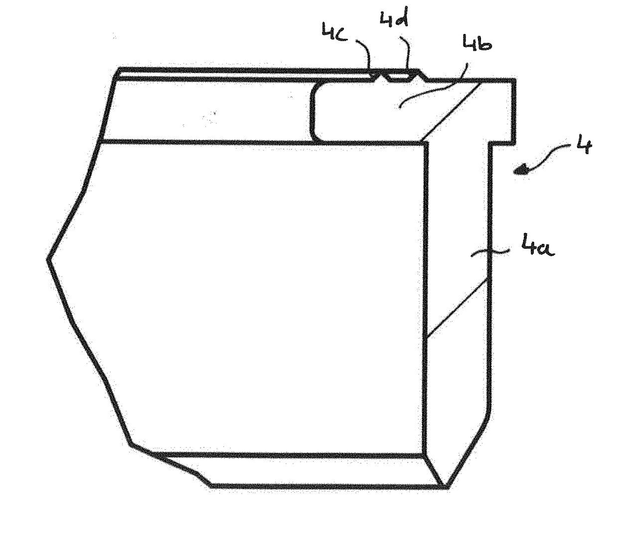
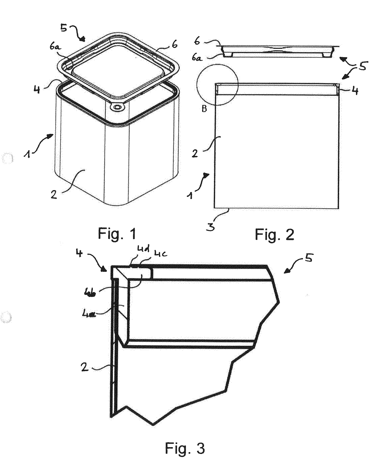
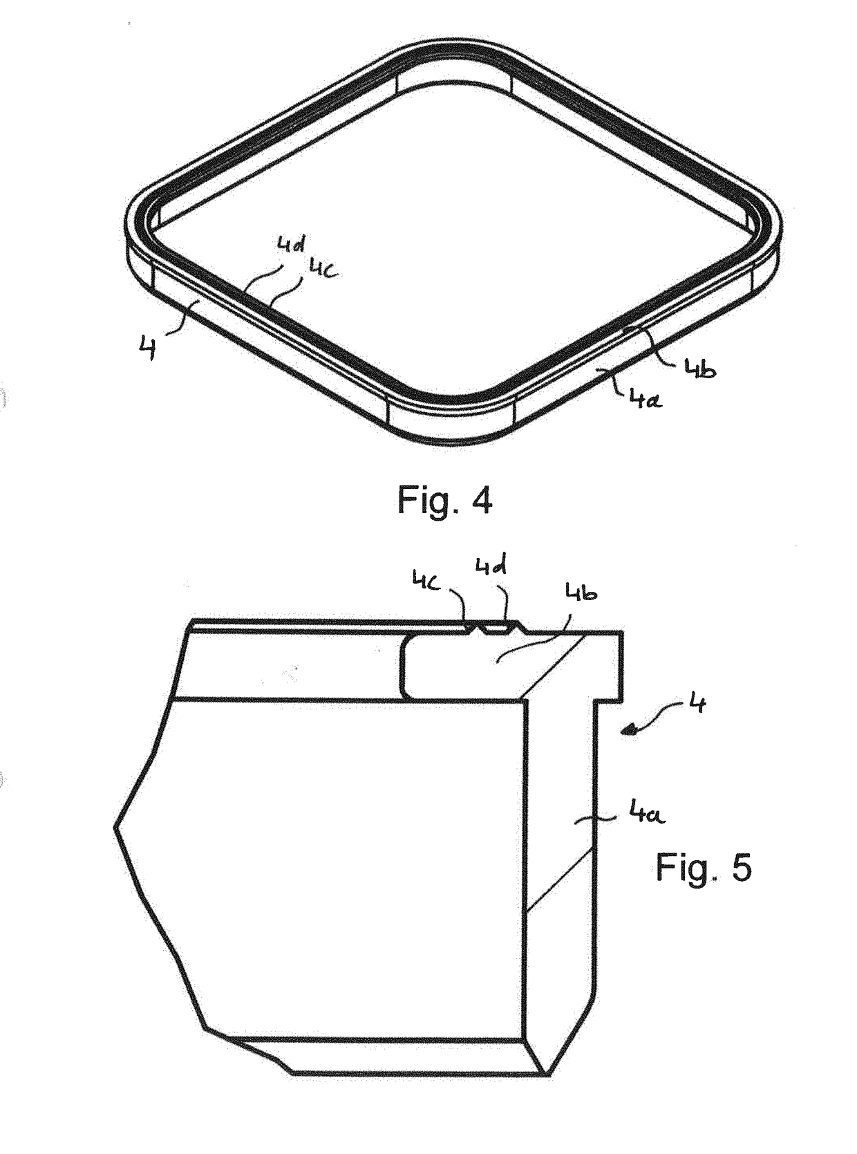
[0042]Referring to the drawings, the packing container schematically shown in FIGS. 1 and 2 and designated by reference number 1 as a whole is formed by a so-called composite can in this exemplary embodiment and has a sleeve 2, which is manufactured, for example, from a paper or cardboard composite and may be provided with an essentially gas-tight and liquid-tight inner lamination with an inner, sealable or weldable cover layer, e.g., one made of polymer-coated aluminum. The sleeve 2, which does not, of course, necessarily have to have the more or less square cross section shown but may also have any other desired cross-sectional shape, e.g., a round, oval, polygonal shape, etc., is closed on its underside in the conventional manner by means of a bottom part 3 (FIG. 2), which may be manufactured itself from corresponding materials just as the sleeve 2, but also of metal, plastic or corresponding composites with high gas-tightness and liquid-tightness.

[0043]A lid ring 4 of a lid asse...


PUM

PropertyMeasurementUnit
Thicknessaaaaaaaaaa
Heightaaaaaaaaaa
Heightaaaaaaaaaa

Abstract

A lid assembly, for a packing container, includes a lid ring of a plasticizable, thermoplastic polymer material and a dimensionally stable lid part, to be placed on the lid ring. The lid part (or the lid ring) has a layer of a peelable plastic material, on a side facing the lid ring (or the lid part), that contains a sealable, thermoplastic polymer or is coated with a cover layer of such a polymer. The lid ring (or the lid part) has an end face facing the lid part (or the lid ring), with two parallel circumferential projections, arranged at a distance of at most 3 mm and sealed to the peelable layer or to the cover layer of the lid part (or of the lid ring). A packing container with such a lid assembly as well as a method for manufacturing same by ultrasonic welding are also provided.

Description

CROSS REFERENCE TO RELATED APPLICATIONS[0001]This application is a U.S. National Phase Application of International Application PCT / EP2015 / 001016 filed May 19, 2015, the entire contents of which are incorporated herein by reference.FIELD OF THE INVENTION[0002]The present invention pertains to a lid assembly for a packing container, with a lid ring consisting of a plasticizable, thermoplastic polymer material and with a dimensionally stable lid part that can be placed on the lid ring, wherein—the lid part has at least one layer of a peelable plastic material on its side facing the lid ring, wherein the peelable layer contains at least one sealable, thermoplastic polymer and / or is coated with a cover layer consisting of such a polymer, and wherein the lid ring has, on its end face facing the lid part, at least one circumferential projection, which is sealed to the peelable layer and / or with the cover layer of the lid part; or—the lid ring has, on its side facing the lid part, at least...

Claims


Application Information

Patent Timeline
IPC IPC(8): B65B51/22B65B7/28B65D77/20
CPCB65B51/225B65B7/2878B65D77/2024B29L2031/7164B29C65/08B29C65/8253B29C66/112B29C66/131B29C66/232B29C66/30223B29C66/542B29C66/73921
Inventor HAUCK, PETERGERBER, EUGENZIMMERMANN, JOACHIMKOCKSCH, HOLGER
Owner SONOCO DEV INC
Learn More