Electro-optical device, method for manufacturing electro-optical device, and electronic apparatus
a manufacturing method and electrooptical technology, applied in the direction of static indicating devices, organic semiconductor devices, instruments, etc., can solve the problems of weakening the bonding strength between the color filter and the sealing layer, and achieve the effect of strengthening the bonding strength of the convex pattern 7 and the color filter layer 8
- Summary
- Abstract
- Description
- Claims
- Application Information
AI Technical Summary
Benefits of technology
Problems solved by technology
Method used
Image
Examples
embodiment
4. Effect of Embodiment
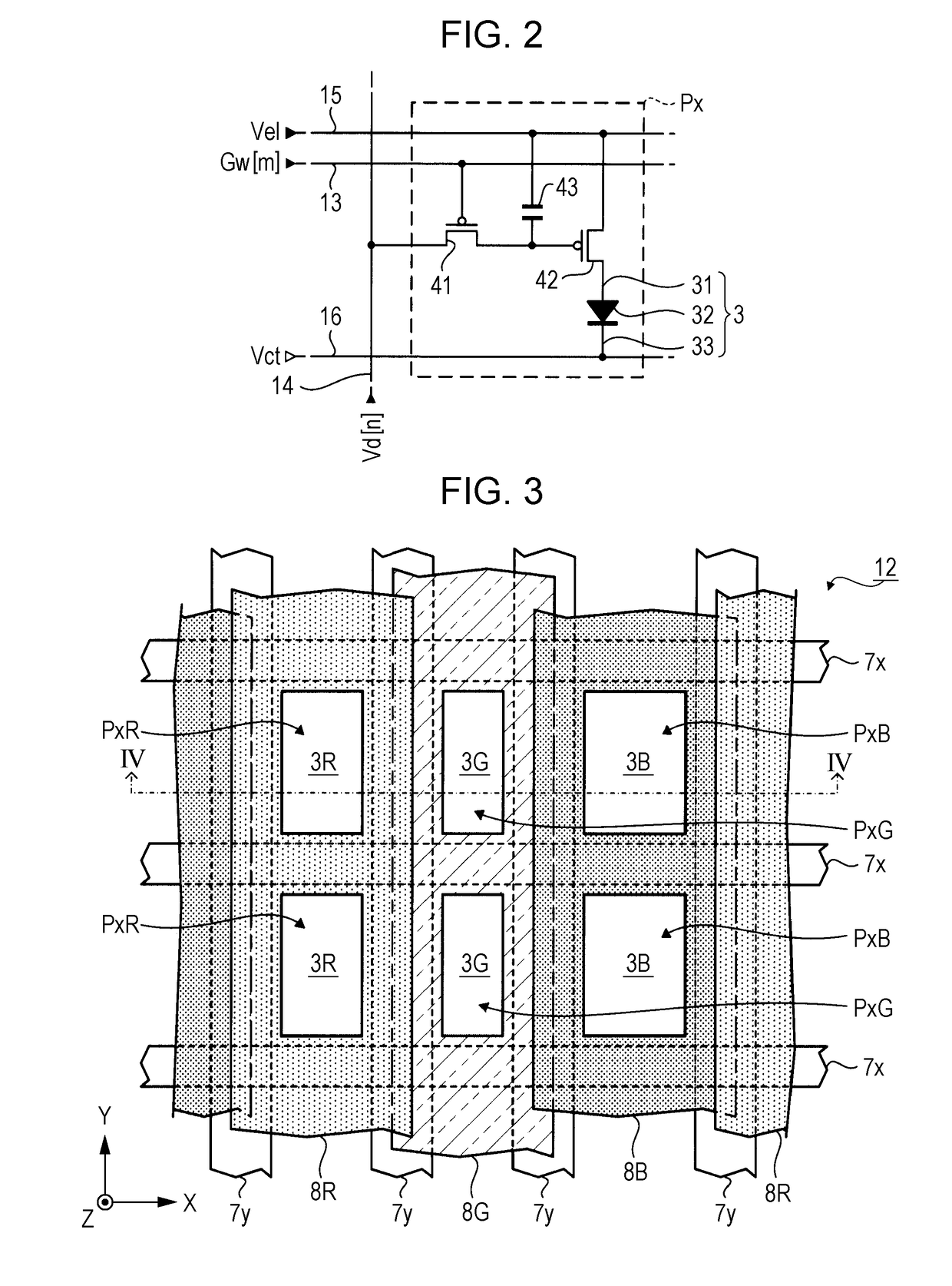
[0102]As described above, in this embodiment, the convex pattern 7 is provided between the sealing layer 60 and the color filter layer 8. As described above, the convex pattern 7 is mainly formed of a photosensitive resin material not containing a coloring material. Generally, the bonding strength of a resin material not containing a coloring material is stronger than the bonding strength of a resin material containing a coloring material. Therefore, as in this embodiment, in a case where a constituent element (hereinafter, referred to as a “constituent on the sealing layer”) formed on the sealing layer 60 includes the convex pattern 7 containing no coloring material in addition to the color filter layer 8 containing a coloring material, the bonding strength of the constituent on the sealing layer to the sealing layer 60 may be increased as compared with the case where the sealing layer 60 is formed only from the color filter layer 8 containing a coloring mate...
modification example
B. MODIFICATION EXAMPLE
[0106]Each of the above embodiments may be variously modified. Specific modification embodiments are exemplified below. Two or more embodiments arbitrarily selected from the following examples may be appropriately merged within a range not mutually contradictory. With respect to elements whose functions and functions are the same as those of the embodiment in the modification examples described below, the reference numerals referred to in the above description are used, and the detailed description thereof will be appropriately omitted.
modification example 1
[0107]In the above-described embodiment, the color filter 8G is exemplified as the first color filter and the color filter 8B or the color filter 8R is exemplified as the second color filter, but the invention is not limited to such an embodiment, the first color filter may be any one of the color filters 8R, 8G, and 8B, and the second color filter may be any one of the color filters 8R, 8G, and 8B. That is, the first color filter and the second color filter may be color filters that transmit light of different colors, or may be color filters that transmit light of the same color. For example, the first color filter may be the color filter 8G provided so as to cover the pixel Px of the m-th row and the n-th column, and the second color filter may be the color filter 8G provided so as to cover the pixel Px of the (m+1)th row and the n-th column.
PUM
 Abstract
Description
Claims
Application Information
 - R&D Engineer
- R&D Manager
- IP Professional
- Industry Leading Data Capabilities
- Powerful AI technology
- Patent DNA Extraction
Browse by: Latest US Patents, China's latest patents, Technical Efficacy Thesaurus, Application Domain, Technology Topic, Popular Technical Reports.
© 2024 PatSnap. All rights reserved.Legal|Privacy policy|Modern Slavery Act Transparency Statement|Sitemap|About US| Contact US: help@patsnap.com


