
Three-dimensional video image display processing device, video information recording medium, video information providing server, and recording medium storing a program

a technology of video image display and video information, which is applied in the direction of optics, instruments, electrical devices, etc., can solve the problems of complex manufacturing process, inability to pick out objects having high spatial frequency components, and difficulty in mechanical positioning, etc., and achieve the effect of complicated manufacturing process

Active Publication Date: 2018-05-10
KANEKO MFG CO LTD
View PDF0 Cites 4 Cited by
  • Summary
  • Abstract
  • Description
  • Claims
  • Application Information

AI Technical Summary

Benefits of technology

The technology described in this patent allows for the use of high definition cameras in an imaging system without compromising the processing speed or causing issues with object recognition or depth estimation. Additionally, the use of low resolution cameras can still improve the overall quality of the image, mitigating the need for post-processing. However, this may come with its own set of challenges, such as difficulty in mechanical positioning and complicated manufacturing processes. Moreover, the patent discusses the drawbacks of using DP matching for depth estimation, and proposes a solution for correcting vertical position misalignment between cameras. Overall, the technology described in this patent improves the overall quality of images captured in an imaging system while simultaneously addressing challenges associated with high definition cameras.

Problems solved by technology

However, providing cameras with different resolutions in the same imaging system has drawbacks such as: (1) when cameras of different resolutions are employed, their shapes are not uniform, making mechanical positioning difficult; and (2) manufacturing processes are more complicated than in cases in which the same imaging element is employed.
Further, if you consider a situation in which the main image is a high definition image and an image having a high spatial frequencies has been input, due to the secondary image having a lower resolution than the main image, objects having high spatial frequency components would not be able to be picked out.
Thus, even though the objects can be sharply ascertained by the viewer, it may not be possible to estimate the depth of these objects.
Such cases result in the need to correct indistinct portions using some other sort of processing.
Further, although an image acquired from the low resolution camera can be obtained that is the same as an image that would be obtained by applying low pass filter processing to an image of the same scene captured by a high resolution camera, phase differences may arise between the image of objects obtained at high resolution and the image of objects obtained at low resolution.
Depth errors may therefore arise when employing DP matching in the stereo algorithm.
However, DP matching calculations are not suitable for parallel processing, and such processing may need to be performed sequentially even when employing a CPU capable of parallel thread processing.
This has the drawbacks of requiring considerable CPU performance to perform DP matching processing in two stages.

Method used


Image

  • Three-dimensional video image display processing device, video information recording medium, video information providing server, and recording medium storing a program
  • Three-dimensional video image display processing device, video information recording medium, video information providing server, and recording medium storing a program
  • Three-dimensional video image display processing device, video information recording medium, video information providing server, and recording medium storing a program

Examples


first exemplary embodiment

2. First Exemplary Embodiment

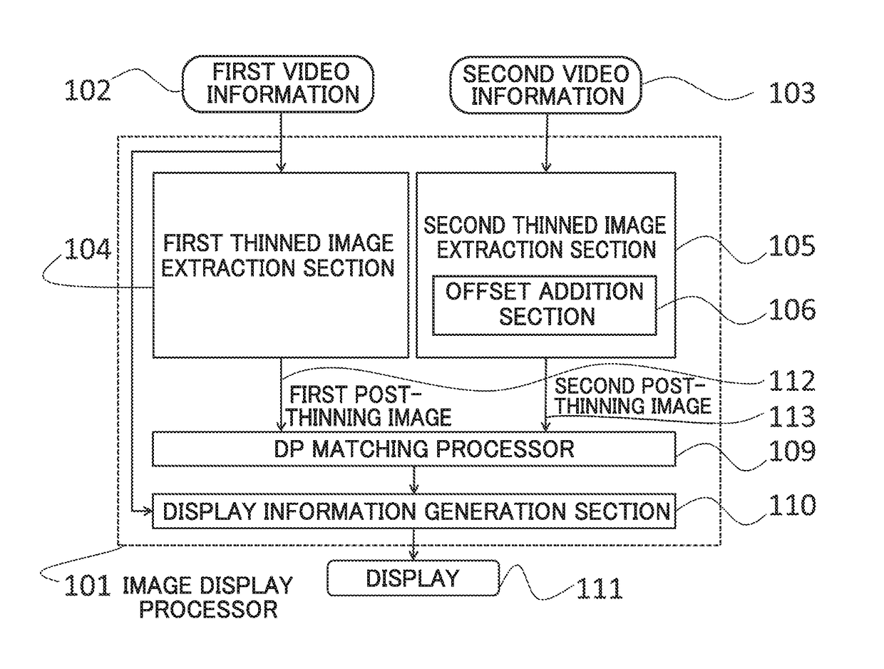
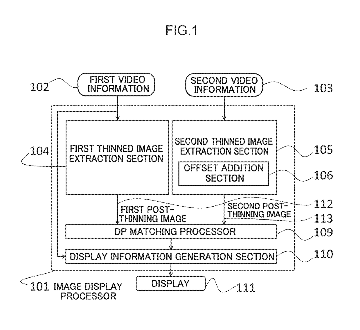
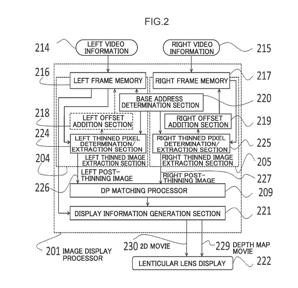
[0091]Next configuration of the present exemplary embodiment will be described, with reference to FIG. 2 and FIG. 3. FIG. 2 is a configuration diagram of the present exemplary embodiment. Further, FIG. 3 is a diagram illustrating the concept of DP cost path. Note that FIG. 1 is also mentioned when discussing a functionality perspective. Further, FIG. 15A and FIG. 15B are also mentioned when describing parallax.

[0092]A relevant section of the present disclosure is implemented by an image display processor 201, and the image display processor is input with left video information 214 and right video information 215 that serve as a basis for stereo viewing. Further, the processing result is output to a display 222.

[0093]2.1. Video Information Input

[0094]The left video information 214 and the right video information 215 are respective items of video information. The left video information 214 and the right video information 215 are simultaneously captured ima...

second exemplary embodiment

3. Second Exemplary Embodiment

[0177]Next, a second exemplary embodiment will be described, with reference to FIG. 4 to FIG. 6.

[0178]The second exemplary embodiment is the first exemplary embodiment in which peripheral configuration to the offset addition section have been modified so as to enable accurate depth estimation even in imaging systems in which precise mounting of cameras is difficult and misalignment arises.

[0179]More precisely, the base address determination section 220, both of the offset addition sections 218, 219, and the thinned pixel determination / extraction sections 224, 225 of the first exemplary embodiment are modified. The modified sections are now discussed, with description of common sections omitted.

[0180]3.1. Offset Addition Section

[0181]3.1.1. Background and Significance of Offset Addition

[0182]The accuracy of the mounting process for the left and right cameras configuring the imaging system has an influence on the vertical direction misalignment between le...

third exemplary embodiment

4. Third Exemplary Embodiment

[0211]Next, a third exemplary embodiment will be described, with reference to FIG. 7 to FIG. 9.

[0212]Similarly to the second exemplary embodiment, in the third exemplary embodiment, precise mounting of the cameras is difficult, and peripheral configuration to the offset addition section is modified to enable accurate depth estimation even when misalignment arises in the imaging system. The main way the third exemplary embodiment differs from the second exemplary embodiment in that a tilting component is also considered in the alignment. More correctly, alignment error in a rotational direction about an axis in a direction normal to an imaging plane of a camera of the imaging system is considered.

[0213]In the present exemplary embodiment, although the configuration is substantially the same as the second exemplary embodiment, the configuration and operation of peripheral configuration to the offset determination section differ.

[0214]4.1. Offset Addition S...


PUM


Abstract

A three-dimensional video image display processing device that causes a three-dimensional image to be displayed on a display by processing a first video information and a second video information. The three-dimensional video image display processing device includes: a DP matching processor that sets a matching scan direction to a direction of a line segment connecting a viewpoint center of the first video information with a viewpoint center of the second video information, and that uses DP matching to obtain depth estimation information for pixels extracted by a first thinned image extraction section and a second thinned image extraction section; and a display information generation section that generates movie display information for the display using video information of either the first video information or the second video information and using the depth estimation information obtained by the DP matching processor.

Description

CROSS-REFERENCE TO RELATED APPLICATION[0001]This application is based on and claims priority under 35 USC 119 from Japanese Patent Application No. 2016-220072 filed on Nov. 10, 2016, which is incorporated by reference herein.BACKGROUNDTechnical Field[0002]The present disclosure relates to a display processing device that displays so as to give a viewer of a display a sense that a stereoscopic object is present. To do so, the display processing device is input with at least two items of video information, performs predetermined processing based on the items of video information, and displays a processing result on a stereo image display.[0003]More precisely, the present disclosure relates to a display processing device that obtains images supplied in at least two continuous time series and sets one image out of these images as a main display image. In a calculation to ascertain a depth needed for stereo image display, by thinning out pixels to increase processing speed and being inge...

Claims


Application Information

Patent Timeline
IPC IPC(8): H04N13/00G02B27/22G02B30/27
CPCH04N13/128H04N13/122H04N13/282H04N13/279G02B27/2214H04N13/0022H04N13/0278H04N13/0282H04N13/0018H04N2013/0081H04N13/139H04N13/106G02B30/27
Inventor HARUYAMA, YOSHIHISA
Owner KANEKO MFG CO LTD
Learn More