A method of identifying a material and/or condition of a material in a borehole

a technology of material and condition, which is applied in the field of surveying of boreholes, can solve the problems of largely qualitative measurement, the annular spaces surrounding the casings may not be completely or perfectly filled, and the pressure control in the borehole is difficult to achieve, so as to reduce the cost of plugging and abandoning operations and reduce the cost of casing recovery

Active Publication Date: 2018-05-10
DEN NORSKE STATS OLJESELSKAP AS
View PDF0 Cites 9 Cited by
  • Summary
  • Abstract
  • Description
  • Claims
  • Application Information

AI Technical Summary

Benefits of technology

[0020]Embodiments of the present invention therefore provide a method that can be used to identify the presence and / or quality of a material such as cement in a borehole. It will be noted that the present invention may employ the so-called “spectral ratio method” in the analysis of a material in a borehole. Advantageously, embodiments of the invention can enable the quality of a material (e.g. cement plug) to be quantified over an interval between two surfaces (i.e. two tubulars or one tubular and the formation), taking into account the bond with both surfaces simultaneously. Furthermore, embodiments of the present invention can take into account the scattering and absorption of a signal along a path in the analysed layer by use of the reference values, which effectively enable these parameters to be calibrated. In addition, using the invention, the quality of the material (e.g. cement) bond can be defined in terms of intrinsic properties of the material.
[0053]By way of the invention, the quality of the cement bond of an outer casing / formation can be determined which is advantageous for the assessment of well integrity. The quality of the cement bond at both the first and second casings / interfaces can be obtained in one logging run. In turn, this can reduce costs in plug and abandonment operations and reduce casing recovery costs. Further advantages of the various features and embodiments the invention will be apparent from the description, drawings and claims.

Problems solved by technology

A difficulty with the casing process in practice is that cement may not completely or perfectly fill the annular spaces surrounding the casings.
Accordingly, there may be gaps where cement has not reached, and potential pathways for fluid from the formation to leak into the borehole, or vice versa, which can create problems for pressure control in the borehole.
This technique has limitations in that the measurement is largely qualitative, as there is no indication of azimuthal cement variations such as channelling and as it is sensitive to the effect of a micro-annulus.
However, existing technology is not able to quantify the quality of a cement plug in an interval between two surfaces, taking into account the bond with both surfaces simultaneously.
Furthermore, existing technology does not take into account the scattering and absorption of a signal along the path in the analysed layer by means of taking into account both types of attenuation: share wave attenuation and flexural wave attenuation.
In addition, the quality of a cement bond is not currently defined in terms of intrinsic properties of the material.

Method used


Image

  • A method of identifying a material and/or condition of a material in a borehole
  • A method of identifying a material and/or condition of a material in a borehole
  • A method of identifying a material and/or condition of a material in a borehole

Examples


Embodiment Construction

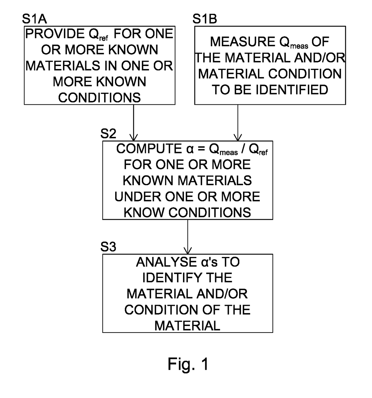
[0074]FIG. 1 shows a flow chart of a method of identifying a material and / or condition of a material in a borehole in accordance with a first embodiment of the invention. The method comprises the following process steps S1A to S3 (numbered correspondingly in the FIG. 1):

[0075]S1A. Provide a reference quality factor (Qreference) for one or more known materials in one or more known conditions.

[0076]S1B. Measure a downhole quality factor (Qmeasured) of the material and / or material condition to be identified.

[0077]It should be noted that steps S1A and S1B need not be performed in a particular order (for example, SIB could be performed before S1A). However, it is more likely that S1A will be performed first and Qreference stored in a computer memory or database.

[0078]S2. Compute a spectral ratio α=(Qmeasured / Qreference) for one or more known materials under one or more known conditions.

[0079]S3. Analyse the spectral ratios to identify the material and / or condition of the material in the ...


PUM


Abstract

A method of identifying a material and / or condition of a material in a borehole is described, together with related apparatus. The material may either be between first and second tubulars or between a first tubular and a wall of the borehole. The method may include providing a reference quality factor (Qreference) for one or more known materials in one or more known conditions and measuring a downhole quality factor (Qmeasured) of the material and / or material condition to be identified. A spectral ratio α=(Qmeasured / Qreference) may then be computed for one or more known materials under one or more known conditions followed by an analysis of the spectral ratios to identify the material and / or condition of the material in the borehole.

Description

TECHNICAL FIELD[0001]The present invention relates to the surveying of a borehole, and in particular, to a method of identifying a material and / or condition of a material in a borehole. In particular variants, the invention relates to determining the quality of a cement bond either between first and second tubulars or between a first tubular and a wall of the borehole.BACKGROUND[0002]Boreholes are formed in the subsurface of the Earth in many contexts. They provide access to the interior of the Earth's crust, as may be desirable for example to construct a well to extract fluids from geological formations in the Earth, or perhaps to explore or make measurements of the subsurface. The borehole is drilled using drilling equipment and is typically cased or lined with tubular sections of casing or lining. The casing or lining can help to support and stabilise the geological formation into which the borehole is drilled in order to prevent collapse of the formation. It may also help to pre...

Claims


Application Information

Patent Timeline
Patent Type & Authority Applications(United States)
IPC IPC(8): E21B47/00G01V1/50
CPCE21B47/0005G01V1/50E21B47/005E21B47/107G01V1/40
Inventor MERCIU, IOAN-ALEXANDRU
Owner DEN NORSKE STATS OLJESELSKAP AS
Why Eureka
Try Eureka