
Rail cum road vehicles (RCRV) and economy rail track-cum-corrugated concrete track to engage with corrugated tread rubber wheels on all roadways

a technology of cum road vehicles and corrugated concrete, which is applied in the direction of railway transportation, climate sustainability, sustainable transportation, etc., can solve the problems of high construction cost of rail tracks, inability to meet the needs of more passenger coaches or wagons, and all developing and poor countries to afford such costly rail net work. , to achieve the effect of reducing travel time, reducing deflection problems, and saving resources

Active Publication Date: 2018-05-10
MUTHUSAMY VENKATACHALAM
View PDF0 Cites 2 Cited by
  • Summary
  • Abstract
  • Description
  • Claims
  • Application Information

AI Technical Summary

Benefits of technology

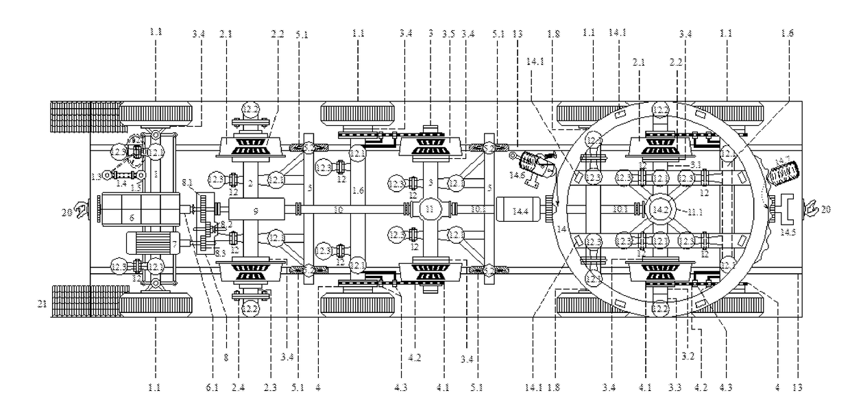
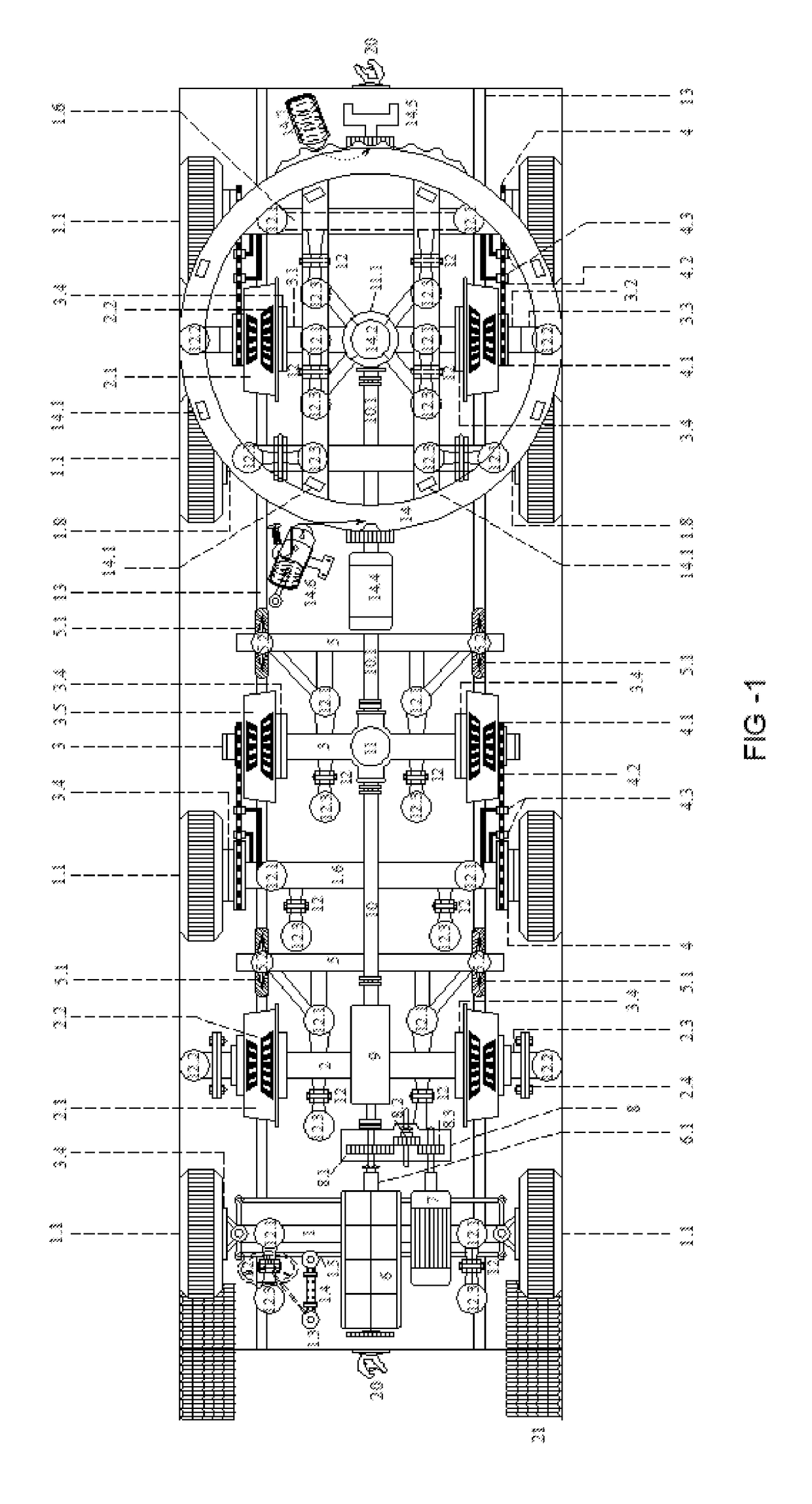
[0019]Therefore the 5th, 6th and 7th axles are fitted under the circular chassis forming a BOGIE which differs from the existing heavy railway bogie. Its diameter is equal to the width of its RCRV with its cross bars to support the axle of flanged steel wheels and axles of rubber wheels with hanger brackets and air bags. Its centre plate with a hole for a stud allows another centre plate with a heavy stud at its centre point fitted underneath the rear side of body chassis frame—to exactly sit into it and then the stud end is tightened with a heavy washer and nut with cotter pin at the bottom of the circular bogie so that it will remain intact with the body chassis frame. This centre plate will share the load of RCRV along with 8 nos, of steel rollers fitted around the top of circular bogie. In between the two centre plates, a greased hard rubber mat will lubricate and reduce noise and vibrations and allow smooth lateral movements of body frame over it at tight curves. This BOGIE with a single axle and a pair of flanged steel wheels is balanced with 4 rubber wheels at its both sides. This “circular bogie”, because it is lighter in weight and serves multi-purpose both on rail track and also on plain road running, it is made as a part and parcel of all long and heavy RCRVs. On rail track, with its smooth automatic circular movements up to about 35 degrees, helps pass through at tight curves and while running on plain roads, with the help of its motorized circular rack and pinion controlled movement, works as “rear steered rubber wheels” while negotiating tight curves, hair pin bends, narrow roads and while parking with self locking arrangement as and when required, all under the control of the driver while running on plain roads.
[0029]In accordance with another embodiment of the present invention, to suit the light weighted RCRVs, an economy rail track with light weight and lesser numbers of sleepers are laid on the hard surface roadways and expressways and so there is no need of any ballast at all. In the existing rail tracks of the heavy rolling stock, because of rail tracks are laid on soft earth and upon ballast and then on the extra heavy sleepers, deflection of rails between the sleepers during running of trains, is an unavoidable perennial problem. Whereas RCRVs will never face such problem as its rail track is laid on hard surface and so deflection problem is totally eliminated. Due to deflection, the heavy existing trains tend to unbearable oscillations with disturbing vibrations and noises in addition to speed reduction and requirement of extra power to make up the power loss due to deflection, whereas it is easy and most economical to construct rail tracks on the existing roadways and expressways because lesser weight rails and lesser numbers of light weighted sleepers will serve the purpose.

Problems solved by technology

But unfortunately the existing railways could not accommodate more passenger coaches or wagons, as they already reached a saturation point.
The main problem with Railways is the high construction cost of their rail tracks.
So, all developing and poor countries could not afford to spend for such costly rail net work.
Also, so far, there was no any alternative economic rail transport technology like RCRV available to the public throughout world.
Regarding freight movement also, either rail or road transportation did not at all satisfy people.
There is enormous delay and theft in rail transport.
So, they seriously warn that the existing world-wide transport net work may collapse and the mankind has to face the aftermath doom and gloom.
When such is the present world's burning crisis, no attempts of any kind have so far been made to revolutionize the heavy, costly, slow moving and obsolete TRAMS / Street rail cars and the killer road vehicles.
But unfortunately all the embodiments of their inventions had been found to be deficient in technologies and unsafe to run on rail tracks as detailed below:
Cumbersome equipments to lift and lower the axles with rubber wheels and steel wheels, then complicated construction of guides to place the vehicle on rail track from plain road, then fitting motors to rubber wheels to move along rail track, without applying mind how the motor will run the vehicle on plain roads without electricity and then other embodiments were orientated with the existing heavy railway bogies.
Therefore roadways commercial vehicles may not suit for broad gauge rail track.
In another dangerous embodiment, both steel wheels and rubber wheels were designed to bear and share the vehicle load equally while running fast, may lead to derailment and more consumption of fuel due to continuous friction / adhesion of rubber wheels on its road track; in another embodiment, convex steel wheels had been designed to run on concave rails and vice versa.
This system will lead to derailment as the natural oscillating tendency of running trains due to wind force and deflection of rails in between sleepers will damage such wheels and rails, which cannot be prevented.
But there was no fool-proof technology applied to safeguard the vehicle while crossing at points of “NO-RAIL” level crossings and other railway crossings where the larger dia rubber wheels need sufficient space or guide to pass through.
This is a very very critical issue.
Still, there will encounter another big problem i.e. the larger dia rubber wheels cover more distance than the smaller dia steel wheels as both are fitted on the same axle.
So when the idly rotating lifted larger dia rubber wheels suddenly lowered and made to take the entire load and run on ramp, it will create a sudden and violent JERK to the entire train leading to imbalance, disturbing passengers.
Further, this kind of frequent disturbances will damage the couplings and joints and rubber wheels may also burst.
Then comes another problem; while the larger dia rubber wheels cross other existing rail tracks, what type of guide was designed, has also not been disclosed; then while moving from loop line to main line and vice versa the same problem encounters and there was no solution explained in those embodiments.
Though the design was simple, fitting and removal of rubber wheels was a laborious job.
So it would be fatal if there was no precision braking system in the R.C.R.Vs.
That was why the heavy TRAMS / street rail cars move very slowly because of its obsolete design and ineffective braking system throughout world.
Therefore all the related prior arts could not succeed to commercialize their patents in the absence of safety, comforts, speed, simplicity, economy and eco-friendliness.
So they are not showing any interest to expand rail net work throughout India at least by encouraging any private innovations of rail-cum-road vehicles because they have the Research, Development and Standards Organization.
Then, on the other side, when already the entire roadways net work is heavily stampeded with the existing multi-million road vehicles, and in the absence of sufficient economic mass transport system, multi-national companies grabbed the opportunity and now fishing in troubled waters.
To sum up, the International Community is very much shocked and disgusted over the existing sluggish, dangerous and obsolete transport system, not able to cope up with the present era of advanced high speed information technology and population outburst.
This acute imbalance seriously hindering industrial and agricultural growth, per capita income and socio-economic development.
However, developed countries, now pointing their fingers towards the highly polluting India, China and Brazil and pressurizing them for more carbon cuts.

Method used


Image

  • Rail cum road vehicles (RCRV) and economy rail track-cum-corrugated concrete track to engage with corrugated tread rubber wheels on all roadways
  • Rail cum road vehicles (RCRV) and economy rail track-cum-corrugated concrete track to engage with corrugated tread rubber wheels on all roadways
  • Rail cum road vehicles (RCRV) and economy rail track-cum-corrugated concrete track to engage with corrugated tread rubber wheels on all roadways

Examples


first embodiment

[0044]FIG. 1 is a plan view of the present invention of Rail cum Road Vehicle being a Large Hybrid Engine Coach, a high capacity independent prime mover on rails or on all roadways. On rails, it can pull plurality of passenger or freight vehicles. It has 4 pairs of rubber wheels 1.1 and 2 pairs of flanged steel wheels 2.1 and one pair of flange-less steel wheels 3.5.

[0045]As shown in F the FIGURES, a solid axle 1 is the front axle with rubber wheels 1.1 and controlled by steering wheel 1.2 and its end pinion 1.3 which is connected to steering end arm 1.4 and fitted to the tie rod 1.5.

[0046]As shown in the FIGURES, in a solid axle 2, flanged steel wheels 2.1 with tapper roller bearings 2.2 are fitted with the support of threaded bush with multiple holed end flange 2.3 to hold steel wheel 2.1. To prevent loosening or tightening of the threaded bush 2.3 over the solid axle, a multiple holed flanged square block with square hole 2.4 matching the axle's square end is fitted and bolted to...

second embodiment

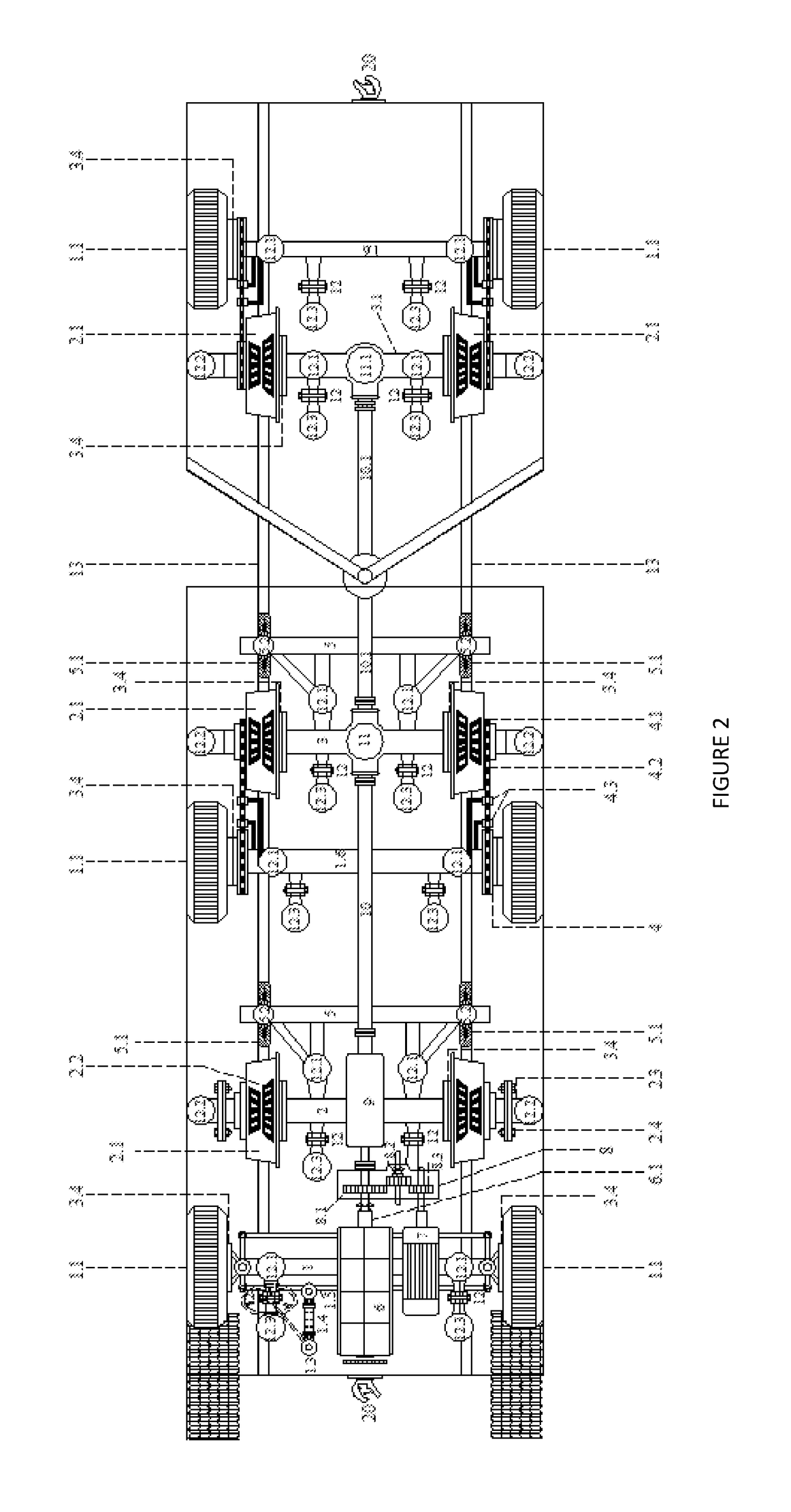
[0056]FIG. 2 is a second embodiment of the present invention of rail cum road vehicles being an Articulate Hybrid Engine Coach. Like FIG. 1, it is also an independent prime mover on rails or on all roadways. It has 3 pairs of rubber wheels 1.1 and 3 pairs of flanged steel wheels 2.1.

[0057]As shown in the FIG. 4, a solid axle 1 is a front axle with rubber wheels 1.1 and controlled by steering wheel 1.2 and pinion 1.3 which is connected to steering end arm 1.4 and fitted to the tie rod 1.5.

[0058]As shown in the FIGURES, in solid axle 2, flanged steel wheels 2.1 with taper roller bearings 2.2 are fitted with the support of threaded bush with multiple holed end flange 2.3 to hold steel wheel 2.1. To prevent loosening or tightening of the threaded bush 2.3 over the solid axle, a multiple holed flanged square block with square hole 2.4 matching the axle's square end is fitted and bolted to the flange of the threaded bush 2.3. This square block also hold the air bag 12.2 on it at solid ste...

third embodiment

[0066]FIG. 3 is the plan view of third embodiment of the present invention of rail cum road vehicles being a Mini Hybrid Engine Coach. This can be used as fast trams. On rail it can haul 3 or 4 passenger or goods vehicles. It has 3 pairs of rubber wheels 1.1 and 2 pairs of flanged steel wheels 2.1.

[0067]As shown in the FIGURES, a solid axle 1 is the front axle with rubber wheels 1.1 and controlled by steering wheel 1.2 and pinion 1.3 which is connected to steering end arm 1.4 and fitted to the tie rod 1.5.

[0068]As shown in the FIGURES, in its solid axle 2, flanged steel wheels 2.1 with taper roller bearings 2.2 are fitted with the support of threaded bush with multiple holed end flange 2.3 to hold steel wheel 2.1. To prevent loosening or tightening of the threaded bush 2.3 over the solid axle, a multiple holed flanged square block with square hole 2.4 matching the axle's square end is fitted and bolted to the flange of the threaded bush 2.3. This square block also hold the air bag 1...


PUM


Abstract

A rail cum Road Vehicle (RCRV) running on rail tracks or on plain roads, includes a gas powered hybrid engine coach linked to and pulling one or several passenger coaches or goods vehicles, all of which in common are fitted with pneumatic rubber wheels, steel wheels, air suspension system with hanger brackets, air brakes and couplers.

Description

CROSS-REFERENCE TO RELATED APPLICATIONS[0001]This application claims a benefit of priority under 35 U.S.C. § 119 as a continuation of U.S. patent application Ser. No. 14 / 423,791 filed on Feb. 25, 2015, which claims priority to PCT / IN2013 / 000491 filed on Aug. 12, 2013, which claims priority to 3588 / CHE / 2012 filed in India on Aug. 30, 2012, which are fully incorporated herein by reference in its entirety.FIELD OF THE INVENTION[0002]The invention relates to Rail-cum-Road Vehicle (RCRV) comprises of Hybrid Engine coach coupled with Trailer-cum-Semi Trailer / Passenger coach / Caravan / Ambulance, Economy Sleeper and Rail Track-cum-corrugated Concrete Track to engage with corrugated tread rubber wheels there for on a portion of all the existing roadways / expressways, for fast mass transportation of passengers and goods within the cities, inter cities and inter states, with facility for door to door loading and delivery of various goods.BACKGROUND OF THE INVENTION[0003]The existing, more than on...

Claims


Application Information

Patent Timeline
Patent Type & Authority Applications(United States)
IPC IPC(8): B60F1/04B61B13/02B60B17/00
CPCY02T30/30B60F1/04B61B13/02B60F1/043B60F2301/00B60B17/00B60F2301/10Y02T30/00
Inventor MUTHUSAMY, VENKATACHALAM
Owner MUTHUSAMY VENKATACHALAM
Learn More