LED optical components

a technology of leds and optical components, applied in the field of optical components, can solve the problems of unsuitable large leds and optical elements in prior designs, and assembly methods that are not suitable for micro-scale devices and components, and achieve the effect of reducing the divergence angl

Active Publication Date: 2018-05-03
X DISPLAY CO TECH LTD
View PDF5 Cites 20 Cited by
  • Summary
  • Abstract
  • Description
  • Claims
  • Application Information

AI Technical Summary

Benefits of technology

[0017]Certain embodiments of the present invention provide micro-scale optical components useful in applications requiring very small sizes, for example in medical or display applications. Because the emission area of the light emitters is relatively small compared to the optical elements, light emitted from the LED optical component can have a reduced divergence angle. In certain embodiments, additional optical components are very small with well-defined structures and well-behaved light emission that complement the optical elements.

Problems solved by technology

However, prior designs use relatively large LEDs and optical elements and assembly methods that are not suitable for micro-scale devices and components.

Method used


Image

  • LED optical components
  • LED optical components
  • LED optical components

Examples


Embodiment Construction

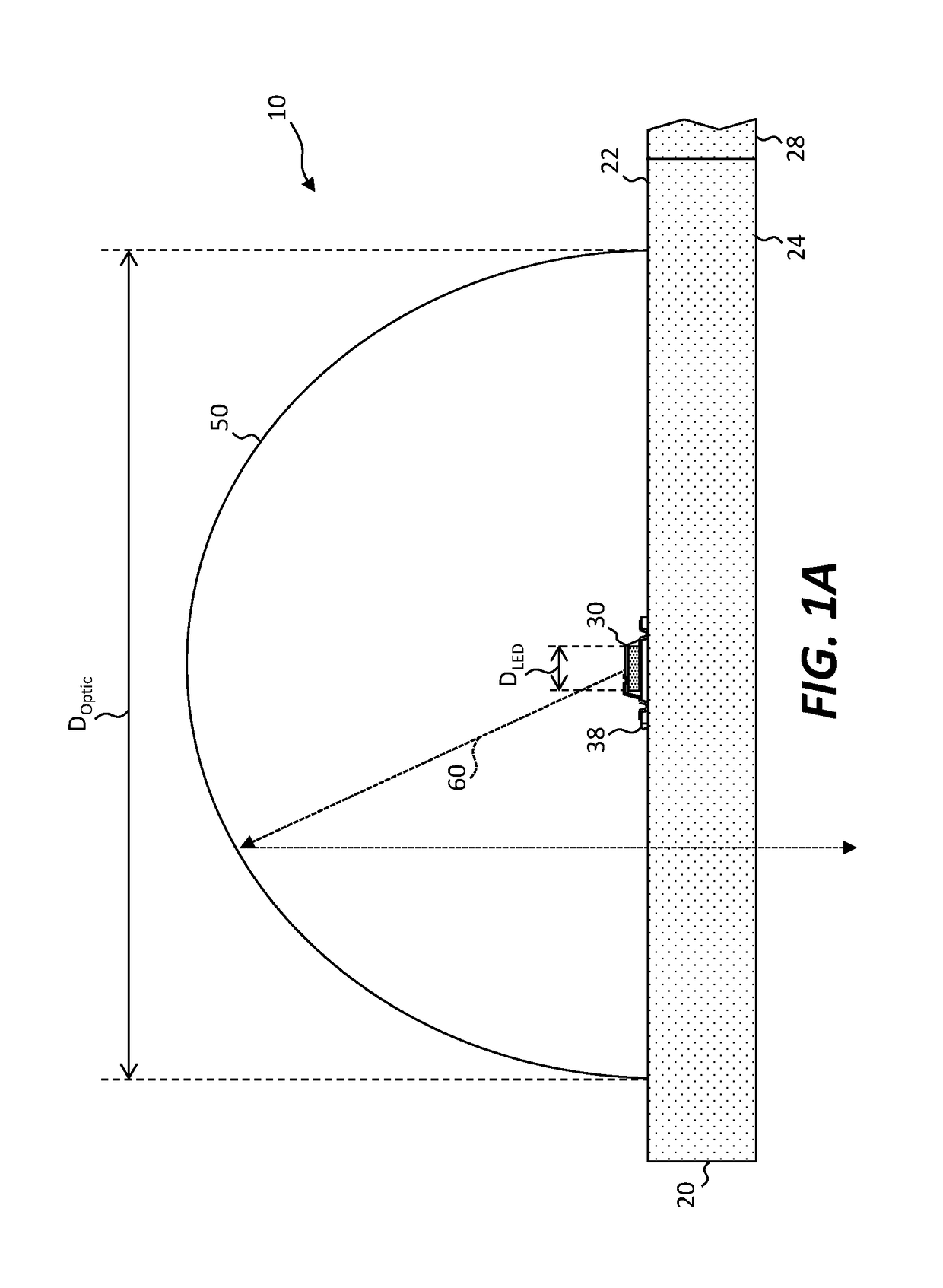
[0067]Embodiments of the present invention include a light-emitting diode (LED or micro-LED) optical component 10 comprising one or more LEDS or micro-LEDs 32 and an optical element 50, as shown in the illustration of FIG. 1A and the detail cross section of FIG. 2. The micro-LED 32 shown in FIG. 2 is on or part of an LED source wafer 40 and can be disposed on an LED optical component 10 (e.g., the LED optical component 10 shown in FIG. 1A) by transfer printing (e.g., micro-transfer printing). A light-emitting volume 33 of each of one or more micro-LEDs 32 can be very small compared to the size or extent of an optical element 50. Thus, in some embodiments, some, all, or a substantial portion of light emission of a micro-LED 32 can be located within, or very near, a focal point, area, or volume of the optical element 50, thereby improving the efficiency of the LED optical component 10. Without wishing to be bound by any particular theory, because physical optical elements are never id...


PUM


Abstract

An light-emitting diode (LED) optical component includes a component substrate having an LED side, an opposite side opposing the LED side, and, optionally, a broken or separated component tether. An LED structure includes an LED and, optionally, a broken or separated LED tether separate from the component substrate. The LED structure is disposed on or adjacent to the LED side of the component substrate and the LED emits light when provided with electrical power. An optical element is disposed at least partly in contact with the component substrate such that at least a portion of the emitted light is incident on the optical element. A second optical element can optionally be disposed between the LED and the component substrate or on the opposite side of the component substrate. An LED optical system includes a system substrate on which one or more LED optical components are disposed. The system substrate can be or include one or more optical elements.

Description

PRIORITY APPLICATION[0001]This application claims the benefit of U.S. Provisional Patent Application No. 62 / 414,085, filed Oct. 28, 2016, titled “LED Optical Component,” the content of which is incorporated by reference herein in its entirety.FIELD OF THE INVENTION[0002]The present invention relates to optical components incorporating micro-transfer printed micro-scale light-emitting diodes (LEDs).BACKGROUND OF THE INVENTION[0003]Light-emitting diodes (LEDs) are commonly used as indicators, light sources, and in large-size, outdoor displays. Because LEDs typically use semiconductor structures having a large optical index, optical structures are frequently employed to avoid trapping light in the semiconductor materials. LEDs are also often used in conjunction with optical elements such as lenses, reflectors, or light pipes. However, prior designs use relatively large LEDs and optical elements and assembly methods that are not suitable for micro-scale devices and components.[0004]Ther...

Claims


Application Information

Patent Timeline
Patent Type & Authority Applications(United States)
IPC IPC(8): F21V19/00F21V7/04
CPCF21V19/0015F21V7/04F21Y2115/10F21Y2113/10G02B19/0066H01L25/0753H01L33/58H01L33/60G02B19/0061H01L2224/24
Inventor BOWER, CHRISTOPHERMEITL, MATTHEWCOK, RONALD S.FISHER, BRENT
Owner X DISPLAY CO TECH LTD
Why Eureka
Try Eureka