


Quick Research
Generate reliable direction feasibility study reports for your R&D in just a few steps.

Technical Q&A
Discover and master advanced knowledge NOW. Basics, ideas, possibilities, all at once.

Find Solutions
As an expert in R&D theories, this can generate solutions to your technical problems instantly.

Evaluate Feasibility
Analyze your overall solution with one click, know your potential R&D risks in advance.

Monitor Landscape
Get weekly tech updates, stay abreast of the latest tech innovations and key insights.
Particle control method
- Summary
- Abstract
- Description
- Claims
- Application Information
AI Technical Summary
Benefits of technology
Problems solved by technology
Method used
Image

Examples
first embodiment
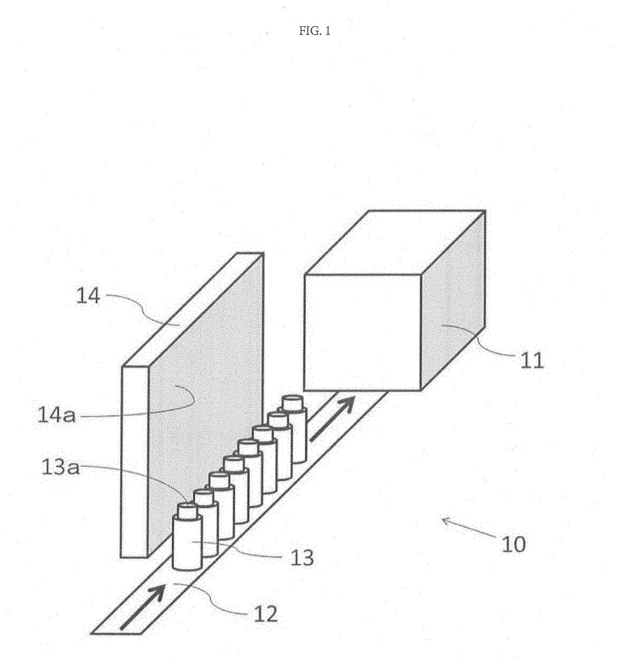
[0057]This first embodiment describes a particle control method in a state where a filling device of pharmaceutical products is disposed inside (clean zone) of an isolator device maintained at Grade A. FIG. 1 is a schematic perspective view illustrating a positional relationship between an oscillation board and a container for filling in a clean zone in this first embodiment. In FIG. 1, an inner wall surface of the isolator device constituting the clean zone is omitted.
[0058]In FIG. 1, in the clean zone 10, a filing device 11 of pharmaceutical products is disposed, and a conveyer 12 travels toward this filling device 11. On this conveyer 12, a plurality of containers for filling (vial bottles) 13 before filling of the pharmaceutical products are arrayed in one row and travel in a direction of the filling device 11. Above the container for filling 13 before filling, an opening portion 13a through which the pharmaceutical products are to be filled is provided. The container for fillin...
second embodiment
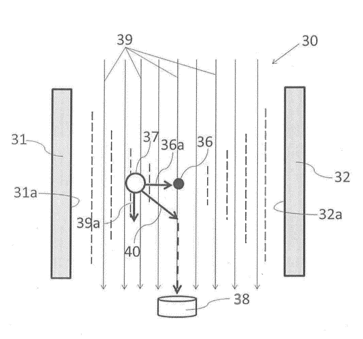
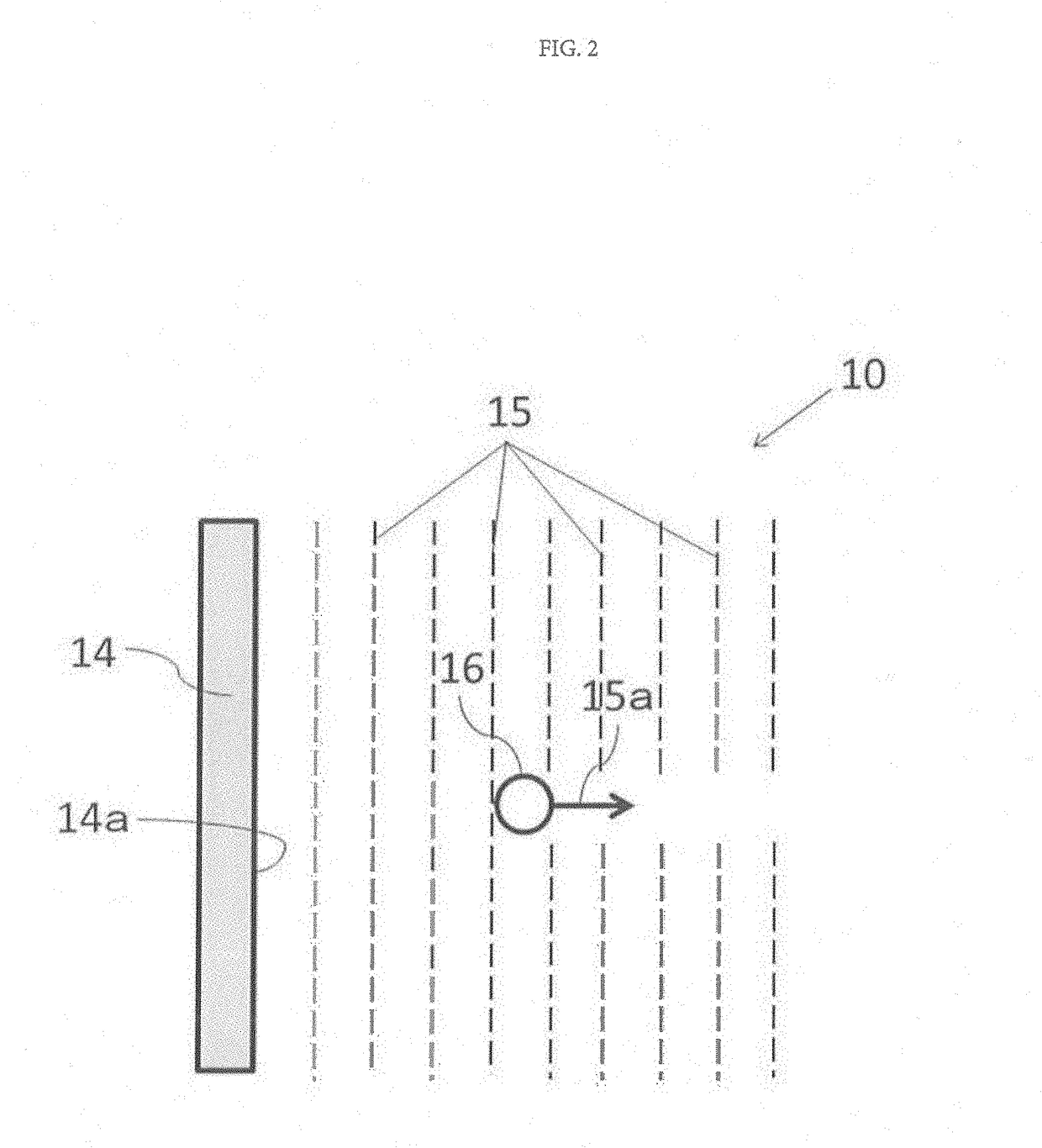
[0072]In this second embodiment, a particle control method when a dust-free state inside (clean zone) of an isolator device maintained at Grade A is measured by a particle counter will be described. Here, the particle counter is also called a particle measuring instrument and refers to a measuring instrument for counting dusts, particles, impurities and the like in the air. In measuring cleanliness in the clean zone, sample air sampled from the capturing port disposed in the clean zone is usually irradiated with a laser beam, and a size and the number of particles are measured from its light scattering intensity.
[0073]In this second embodiment, the laminar flow flows through the clean zone, and there is an extremely small quantity of particles descending linearly on the laminar flow from the upper side toward the lower side in the clean zone in the clean air supplied into the clean zone through the HEPA filter. On the other hand, the capturing port of the particle counter is opened ...
third embodiment
[0084]In this third embodiment, a particle control method when the floating bacteria contained in the particles present in an extremely small quantity inside (clean zone) of the isolator device maintained at Grade A are counted by a floating bacteria counter will be described. In this third embodiment below, even if it is described simply as a “particle”, it is assumed to refer to the “particles including floating bacteria”.
[0085]Here, the floating bacteria counter refers to a measuring instrument for counting the floating bacteria contained in dusts or particles in the air similarly to the particle counter in the second embodiment. Particularly, in this third embodiment, a floating bacteria counter used in Rapid Microbiological Methods (RMM) is employed. In order to measure the floating bacteria in the clean zone by using this floating bacteria counter, sample air sampled from the capturing port disposed in the clean zone is usually irradiated with a laser excited fluorescence (LIF...
PUM
| Property | Measurement | Unit |
|---|---|---|
| Pressure | aaaaa | aaaaa |
| Distance | aaaaa | aaaaa |
| Acoustic properties | aaaaa | aaaaa |
Abstract
Description
Claims
Application Information
 - R&D Engineer
- R&D Manager
- IP Professional
- Industry Leading Data Capabilities
- Powerful AI technology
- Patent DNA Extraction
Browse by: Latest US Patents, China's latest patents, Technical Efficacy Thesaurus, Application Domain, Technology Topic, Popular Technical Reports.
© 2024 PatSnap. All rights reserved.Legal|Privacy policy|Modern Slavery Act Transparency Statement|Sitemap|About US| Contact US: help@patsnap.com