Angular Velocity Measuring Device and Relative Angular Velocity Measuring Device

Inactive Publication Date: 2018-03-29
TOYOTA JIDOSHA KK
View PDF0 Cites 6 Cited by
  • Summary
  • Abstract
  • Description
  • Claims
  • Application Information

AI Technical Summary

Benefits of technology

The patent describes a device that can accurately measure the speed of rotation of a gear, even if the gear does not have regular teeth. The device uses a special sensor to measure the output of a noiseless signal, which is then combined with another sensor to create a high-quality output waveform that is not affected by noise. This allows for very precise measurement of the gear's speed, even during tooth hammering or other noise events. The device can also be used to measure the relative angle between gears by attaching it to a pair of gears. The technical effects of the patent are the suppression of noise and the improved accuracy of angular velocity measurements in gears without regular teeth.

Problems solved by technology

In measuring a rotational speed of a gear that is mounted in a real machine such as a vehicle or the like, according to the measurement method utilizing the rotary encoder, the rotary encoder needs to be directly installed on a rotary shaft, so the space for installation is limited.
Besides, in the case of the real machine, the installation itself of the rotary encoder in a measurable manner in a structure with a measured object in rotation is difficult.
According to the measurement method utilizing the photo interrupter, a light path needs to be ensured, and the place for installation is limited due to the great influence of the environment.
Therefore, changes in speed among the acquired sensor signals cannot be grasped with high resolution capability.
As a result, it is difficult to accurately calculate fluctuations in the rotational speed.
Then, the relative angular velocity of gears that are mounted to mesh with each other cannot be accurately measured.
For example, it is difficult to accurately acquire movements of tooth flanks of the gears into / out of contact with each other, and carry out an adjustment for reducing tooth hammering noise etc.
Incidentally, as will be described later, this problem is also caused in a similar manner in the angular velocity measuring device according to the measurement method utilizing the photo interrupter, in the case of a gear that does not have a precisely sinusoidal tooth flank shape.
In particular, the noise in the form of third-order harmonic components influences the accuracy in measuring the angular velocity.

Method used


Image

  • Angular Velocity Measuring Device and Relative Angular Velocity Measuring Device
  • Angular Velocity Measuring Device and Relative Angular Velocity Measuring Device
  • Angular Velocity Measuring Device and Relative Angular Velocity Measuring Device

Examples


Embodiment Construction

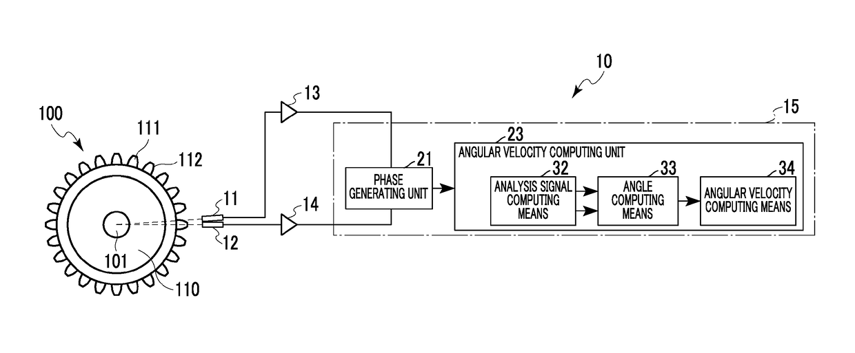
[0052]The embodiments will be described hereinafter in detail with reference to the drawings. FIGS. 1 to 13A-C are views showing an angular velocity measuring device according to one of the embodiments.

[0053]In FIG. 1, an angular velocity measuring device 10 is mounted in, for example, a vehicle, and is installed for the purpose of measuring a gear 100 that is incorporated in a motive power transmission mechanism that transmits motive power from a motive power source such as an internal combustion engine or the like, such as a transmission, a differential device or the like. Incidentally, this angular velocity measuring device 10 may be mounted in a real machine such as a vehicle or the like in a steadily usable manner, or can also be used by being temporarily installed in adjusting the setting.

[0054]It should be noted herein that the gear 100 is formed such that a body portion 110 and a plurality of meshing teeth 111 rotate integrally with a rotary shaft 101. The body portion 110 h...


PUM


Abstract

An angular velocity measuring device measures an angular velocity of a gear that is fixed to a rotary shaft. The angular velocity measuring device includes a pair of magnetic sensors that are arranged at positions facing a tooth flank of the gear and that detect a shape of the tooth flank in a noncontact manner, and a computation unit that is configured to generate a waveform obtained by synthesizing output detection signals of the pair of the magnetic sensors with each other and output an output waveform and calculate the angular velocity of the gear from the output waveform. The magnetic sensors are arranged such that the output detection signals are offset from each other by {(n−1)+(⅙)} pitches when one pitch is defined as one cycle of the shape of the tooth flank in a circumferential direction of the gear.

Description

INCORPORATION BY REFERENCE[0001]The disclosure of Japanese Patent Application No. 2016-192120 filed on Sep. 29, 2016 including the specification, drawings and abstract is incorporated herein by reference in its entirety.BACKGROUND1. Technical Field[0002]The present disclosure relates to an angular velocity measuring device and a relative angular velocity measuring device that accurately measure a rotational speed of a gear.2. Description of Related Art[0003]A rotational speed of a gear is measured after appropriately selecting one among various measurement methods such as a method utilizing a rotary encoder, a method utilizing a photo interrupter, a method utilizing a magnetic sensor, and the like.[0004]In measuring a rotational speed of a gear that is mounted in a real machine such as a vehicle or the like, according to the measurement method utilizing the rotary encoder, the rotary encoder needs to be directly installed on a rotary shaft, so the space for installation is limited. ...

Claims


Application Information

Patent Timeline
IPC IPC(8): G01P3/44
CPCG01P3/44G01P3/488G01P3/489
Inventor HOJO, KATSUYUKI
Owner TOYOTA JIDOSHA KK
Why Eureka
Try Eureka